To "start off on the right foot" – given that the reader might not know the reason why in some types of telescope must create a secondary mirror of convex type, we make a "panoramic" on the evolution of telescopes that led to the use of this type of mirror.

The refractor telescopes were the first to appear from 1609 (Galileo), followed in 1680 from Newtonian Reflector telescope.
But the refractor remained, and still it remains, a type of limited opening telescope, penalizing the useful magnification and therefore the definition of particular extremes, otherwise much better visible with reflector type telescopes, whose goal is a mirror for the most part parabolic, simple and easy to realize also in large diameters, which requires a small flat mirror for the lateral deflection of the astronomical vision toward the eyepiece.
The increase in the diameter of the primary mirrors, and with it that of their focal length determined very long optical tubes.
In the years of Newton's discovery it appeared the project of two telescopes in alternative configurations, Gregory and Cassegrain, characterized by shorter tube than that of Newton, thanks to the assembly of a secondary mirror no longer plan, but can reflect “farther” the received light cone, returning it over the primary mirror, through the hole that it is therefore necessary to drill at the center of the latter, where the eye.
The family of these telescopes are spread over time, and each new member took the name of its configuration by technicians that planned, some of which (with the exception of variants catadioptric) are the following:
- Gregory (James Gregory 1663): primary parabolic - secondary elliptical concave (correct spherical aberration and coma weak). Rarely used. Its tube, despite being shorter than that of a Newton, It is longer than the other versions here indicated below, but it is the only one to offer the advantage of a vision straightened, good for terrestrial use,
- Cassegrain (Laurent Cassegrain 1672): Primary parabolic - convex hyperbolic secondary (ab.sferica correct coma and weak)
- Ritchey-Chretien (1922): Primary hyperbolic - convex hyperbolic secondary (correct spherical aberration and coma null)
- Dall-Kirkham (1951): Primary elliptical - secondary convex spherical (ab.sferica correct and strong coma)
- Pressman Camichel (1954): Primary spherical - secondary elliptical convex (ab.sferica correct and huge coma).
The present availability of means and materials greatly wider than that of the past, It makes possible the manual manufacturing / crafts of this kind of challenging the Newtonian telescopes, even by an audience of a few savvy and enterprising enthusiasts.
The main difficulty for these fans unfortunately remains the impossible finding in Italian language help texts that explain how to create mirrors for these telescopes.
The most popular literature on this subject is Too bad English or French, and the most common object regards the explanations for the realization of a concave spherical mirror / convex, starting from rubbing with wet abrasive interposed, of two glass discs, one of them with the processing becomes concave and the other will thus present the same curvature but convex.
The spherical (see its section such as black dotted circle in the following figure) It is the most easily accomplished with great precision, from which it is technically more convenient to realize in sequence each of the other conical shapes gradually more flared or deformed ball, that are: The elliptical shape prolate (its section is in blue color) ; the dish (in green) ; and hyperbolic (in red).
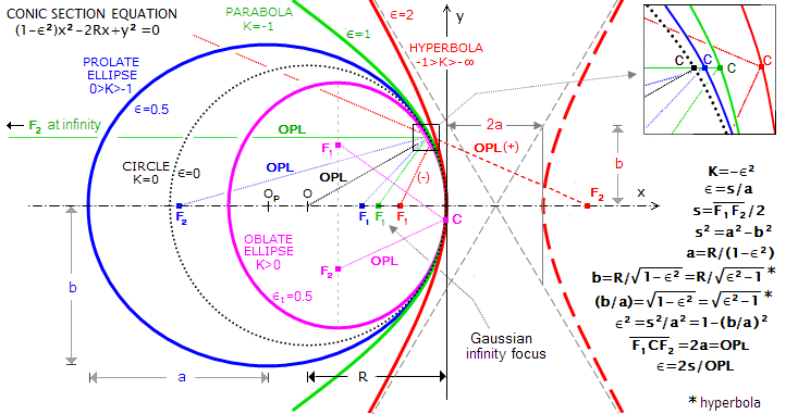
Fig. 1 – conic Sections
Given that in Italian there is not a valid method of realization for a convex mirror of elliptical section,, I translate here a chapter of the book in French titled “Realize your telescope” di Karine and Jean Marc Lecleire.
(NOTE: NOTES: For non-Italian language readers,, direct reading of the chapter in the indicated book is recommended, , in order to avoid errors generated by what would be a terrible double translation made by automatic softwares).
The chapter describes the construction of a convex secondary mirror for a Cassegrain telescope F12. But regardless of the type of recipient described Telescope Mirror, it is still a practical guide that allows you to understand the relationship between the design data and the realization practice manual, that in this way is suitably transferable to the construction of other types of secondary mirrors of convex shape.
————————————-
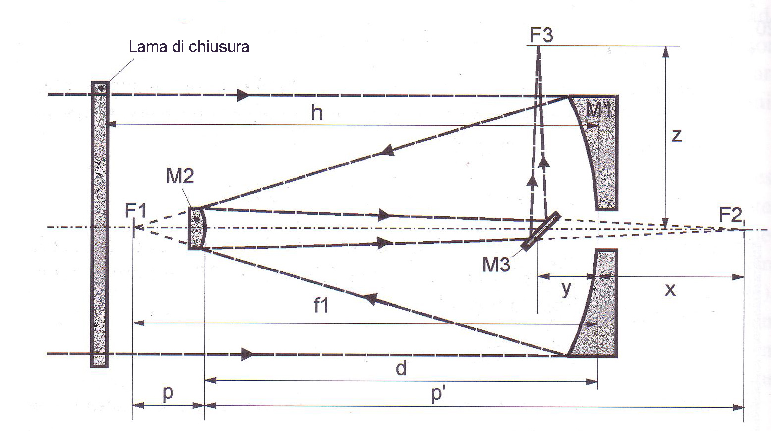
Fig. 1 (p.196- The telescope described in which fabricating the secondary, M1 has primary O305, 305mm Outer Ø, e 300 optical diameter, con ROC =1800mm; Focal F1 = 900mm; arrow 6,25mm; holes Ø45mm mirror
(p.225-228)
The secondary mirror is the most delicate piece to achieve in a Cassegrain telescope. The convexity is not directly controllable with the Foucault method as for the primary mirror. an interferometric method is used instead (as for secondary plans, with diffraction fringes of light of a sodium lamp) to compare the convex mirror of a gauge having the same radius of the concave.
MANUFACTURING PROCEDURE
The work of the secondary mirror is held according to the following steps:
- slotting, rodare refine and polish the convex mirror as a concave mirror. The mirror becomes convex and concave disc becomes caliber. In the case of this telescope, the arrow of the mirror diameter is 1,78 millimeters in 95 millimeters from the edge.
- After polishing the bottom of each glass, polishing the two rotary discs to give them the same curvature.
- Realize the spherical shape of the concave mirror (caliber). At concave caliber, in the case of very deformed to a mirror control (for example, the secondary of this T300), We must give shape complementary to the convex hyperbolic in order to control the latter in optimal conditions (see final paragraph entitled "When the largest gap exceeds Epsilon 2 fringe ").
- Giving first a spherical shape and then the convex hyperbolic mirror and check for colored interference fringes, with the help of the concave caliber.
FROM ROUGH GRINDING TO THE REFINEMENT
The working methods are those used for normal parabolic mirror.
The important points to note are:
- It is advisable to take a hard tool (that will become concave) larger diameter (4 or 5 mm) compared to the mirror (which will be convex) to avoid being disturbed by a possible defect of the concave edge during polishing of the pieces.
- Be careful to avoid splinters that can form on the edge of convex parts during roughing. Realize for this one off chamfer 4 until 5 mm, which must be maintained throughout the work. Also, do not make too long strokes on the tool supporting concave.
- At the end of roughing, the arrow must be respected with a precision better hundredth of a millimeter. The focal length and the values of p and p’ (see figure 1) They are very sensitive to changes in the radius of curvature of the secondary mirror, measured using one spherometer ring (see drawing below).
- When you reach the value of the arrow, We must continue to alternate dried with mirror above and below mirror, to preserve the curvature of the faces until the end of ripening. In this sentence, in the running surfaces touching each other well on the entire surface and do not observe air bubbles inside the two glass discs.
SPHEROMETER RING
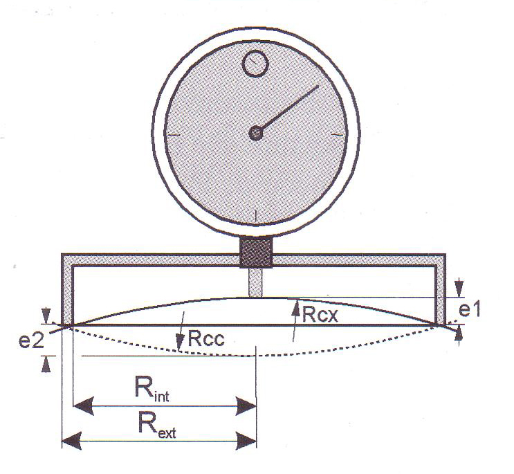
Fig.2 – Sferometro ring used to control the radius of curvature of the small diameter mirrors
The radius of curvature of a convex disc Rcx It is calculated as follows:
For a concave mirror is calculated Rcc:
If we replace the ring with three spheres diameter b placed at a distance D from the sensor, the radius of curvature R is:
(where will + b for the convex, e – b the concave)
WORKING THE BACK OF THE PIECES
In order to carry out the control with the interference fringes, it is necessary that the back of each piece is made transparent: summarily Refine the back of the mirror is that the tool then polish individually rubbing the back of each piece of a coated fabric of floor polishing tool (pressing of a piece of woolen fabric on the hot pitch) very load of cerium oxide. The operation lasts for fifteen to thirty minutes. The surface quality and the flatness of the back does not affect the shape of the interference fringes of the control.
POLISHING MIRROR CONVEX AND GAUGE CONCAVO
Make two polishing tools plaster, the first convex to polish the concave disk; the second concave to polish the convex disc.
Begin to polish uniformly the concave disc and the convex caliber with their respective complementary tools (working for each disc 20 or 30 minutes, with W racing 1/3 D) to perform a first control interferential. After thoroughly cleaning the convex and concave mirror caliber with a brush of hairs rate, put three cloves of cigarette paper at 120 ° on the periphery of the concave piece. Then lay the convex piece above the concave caliber. Run the check exactly as you do for a flat mirror, illuminating the discs with a spectral lamp placed behind a diffuser.
If the curvature of the two discs are exactly the same, They will observe interference fringes of the straight lines and regularly spaced. If the curvatures are different, concentric circular fringes are observed. Pressing your finger on the upper disk, it is determined whether the rings are convex (fringes out from the disc and touch each other at the center) o concavi (fringes fall and the discs touch each other at the edge). If the difference of curvature is greater than 7 or 8 fringe, It should incorporate the two pieces to the last abrasive grain used (working the concave glass over whether it is convex fringes, and viceversa). A concave defect is more difficult to modify a convex defect. It 'also desirable to start polishing with its convexity 3 or 4 fringe. In this sentence, also check the spherical concave shape with a Foucault tester and a mask Couder. Touch up any major faults in the concave parts before further polishing the convex mirror.
STARTS POLISHING
At first, perform three-quarters of the convex mirror polishing to give it the same as the caliber radius of curvature. If you observe the convex fringes, position the mirror above its polishing tool to make it less deep its curvature (make it more convex or less concave mirror). If not, place it under the polishing tool to perform the reverse operation (to make it more convex or less deep). Run polishing cycles 20 minutes doing ran straight or W amplitude 2/3 until 3/4 the maximum amplitude diameter (with a transverse swiveling out of 1/8 D) without trying to support in order to run. If this scheme creates a deformation on the mirror, it is necessary to unite the surface with the usual break-in, performing racing W amplitude 1/3 D.
Polish the caliber equally by applying the same tweaks.
It is not necessary to polish completely because it is easier to vary the radius of curvature of a workpiece, if its surface is still gray.
Another method to reduce or reinforce the curvature of a surface consists in sguarnire the tool according to a particular track: By preventing the contact with the glass of the pitch to the tool center or in the periphery to operate inversely. You can get yourself what compressing pitch on a figure of cartonboard.
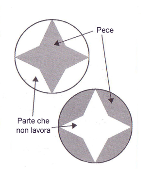
Fig. 3 – patina Forms
Examples of tool positive or negative star obtained after pressing a cardboard mask: the gray areas correspond to the pitch of the surface in contact with the mirror. Up: tool to decrease the convexity (with the central star in relief); Down: Tool to increase, (with raised edge and star encased).
OBTAIN THE SPHERICAL SHAPE OF THE CALIBER
When the curvatures of the two convex and concave caliber mirror glasses are very close (from 1 until 2 fringe rings), it proceeds to processing of the caliber of the concave sphere.
In order to serve as a reference for the convex mirror, this piece must reach an accuracy of lambda/10 in control with Foucault.
To avoid introducing extra-axial aberrations, Foucault tester on the blade must be brought to a distance of 10 or max 15mm from the slit. The operation is feasible with both a mechanical modification unit, that with the addition of a reflection with semitransparent mirror 45 °, that with a separator cube "beam splitter"
The verification of the spherical curvature of the caliber must be carried out using one of Couder screen 3 or 4 zones.
The draft measured on each zone corresponds directly to the "small measures" used for calculating the aberration Longitudinal to the center of curvature Alc
Alc= Reduced measures - K (K choosing positive or negative, as a Foucault test).
Once you have the caliber concave, It is necessary to refine the polishing of the convex mirror.
The interference fringes observed should be straight. In this sentence, the convex mirror must be perfectly polished, without the presence of gray.
REALIZATION OF FORM hyperbolic MIRROR CONVEX
The calculation of the deformation is still done with the help of already seen fig 1.
(196-197)
The telescope has described primary M1 Ø305, 305mm Ø external, e 300 optical diameter, with ROC =1800mm; focal F1 =900mm; arrow 6,25mm; perforated mirror Ø45mm
magnification G given from the secondary M2, is the ratio of the resulting focal of the instrument and the focal of the only primary.
In this project G = 3600/900 = 4.
The focal ratio of the final combination 12.
The distance p between the optical surface of the convex secondary and the focus F1 is:
p = (F1 x)/(G 1).
Where x is the distance between the surface of the primary and secondary focus F2. In the present case p=238mm
The distance of the dimension O, between the center of the center of the primary and secondary is d = F1 p.In the present case it is 662 mm. The distance p’ between the area of the secondary mirror and focus F2 (knowing that the magnification G the secondary mirror is given by p'/p), you have p’=p*Gwith p’ which is = 952 mm.
The diameter D2 the convex mirror is defined with:
D2 = (D1 • p / F1) + d • tan a
Where a the telescope is covered field.
You choose a full light field at the Cassegrain focus equal to the diagonal of a photographic negative, formato 24 x 36 mm, calculating it as follows:
α = arctan (of the root of (24^2 36^2)) / 3600
or 41 arcmin.
We can thus calculate the diameter of the convex secondary D2, which becomes 87 mm, and the Mechanical diameter = 95 mm.
The radius of curvature R2 the secondary is given by the formula R 2 = 2 • P • G /(G-1), or R2=634,67 mm.
This mirror is a hyperboloid of revolution,and its deformation coefficient B2 It is calculated by placing b2 = – ( (G 1) / (G-1) )^2. I our case b2 = -2,78 (for the primary b1 = -1).
(228-229)
Found b2 = -2,78. It calculates the deviation in relation to the tangent sphere the top of the mirror and secant to the edge of the opening of the useful height h, with the use of the formula:
Where Y is the distance from the center of the mirror and R2 It is the radius of curvature of the secondary mirror. The maximum gap e You are obtained for the high zone 0.707 calculating it with the following formula:
e = (B2 / 32)(h^4 / R 2 ^ 3)
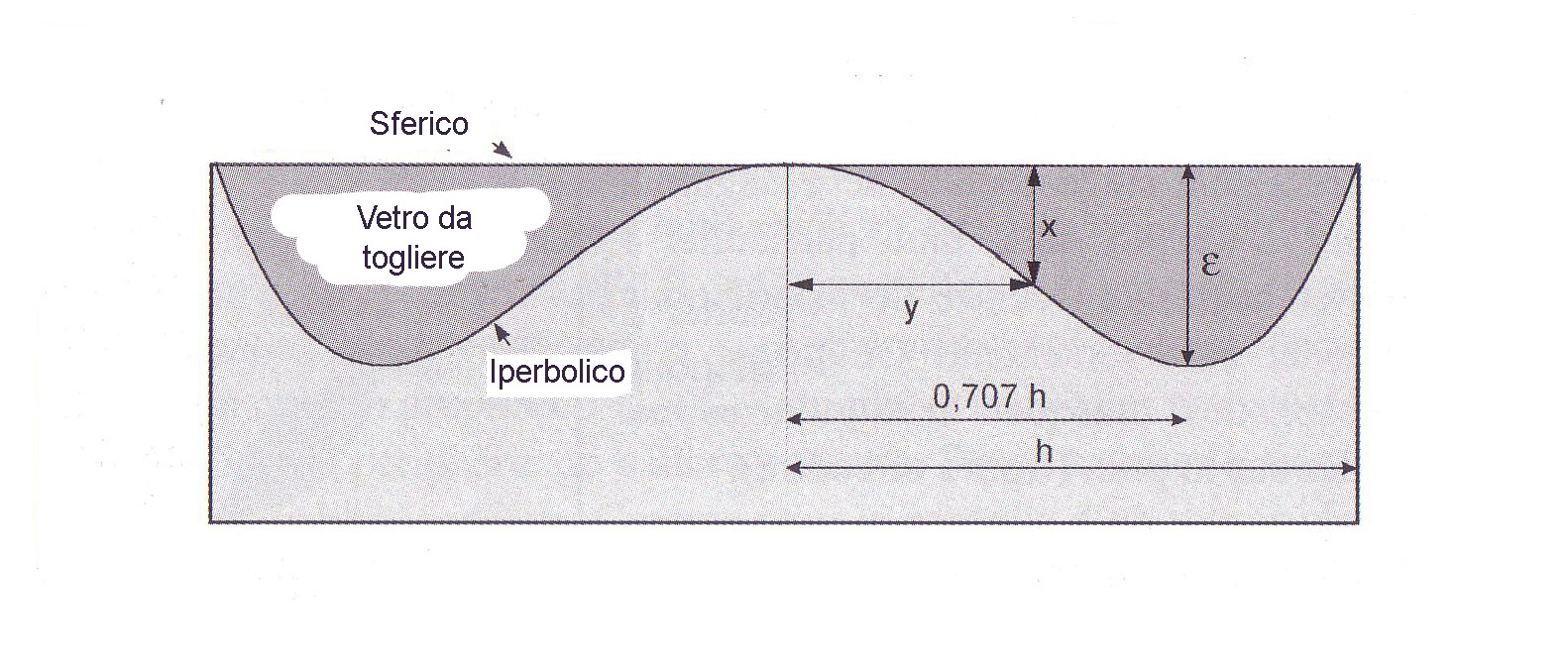
Fig. 4 – mirror forms comparative
Comparative Forms hyperbolic mirror and the sphere having the same radius of curvature (the heights are greatly amplified for Readability). Epsilon The maximum deviation is obtained for the height region 0.7.
When controlling a hyperbolic convex mirror of a concave spherical sundial of the fringe pattern corresponds to the hyperbolic contour shown in the figure above.
The general polishing procedure consists in working the convex mirror by means of a tool in unprotected inversely proportional to wear so as to perform. You can also use a tool in the shape of petals, or still a tool having a diameter circular crown 0,7 times that of the mirror.
Note: Here we talk about optical diameter. Which means that when checking or calculates, the excess part of the optical diameter should be disregarded, if the outer diameter of the mirror is larger than the optical diameter.
For small deformations (< a fringe and a half), the realization poses no problem. Follow local regulations for a few minutes with a little 'polishing even with the thumb. For the control of the convex in relation to the concave spherical, cut a paper pattern whose shape is defined by the equation above, see figure 4.
Then determine the polishing touches for comparison Fringe sundial with cardboard model.
For large deformations (this is the case with the mirror of T300 in which the maximum deviation is Epsilon -1,22 microns, or 4.14 fringes for lambda = 0,589 nm), constitute a series of tools in crowns centered on the area 0,7 but of different widths. Gradually deforming the convex mirror, being careful not to create fringes "in steps" . To avoid this problem, the edge of the rings must be irregular (notched as lace) and the pressure of hands on the very moderate tool.
When the largest gap exceeds Epsilon 2 fringe, the sundial fringe is too distorted to allow a reliable measurement, and then the control method of such a mirror is a bit’ different from the last.
We must therefore, starting from existing spherical, to achieve a concave hyperbolic mirror having the same deformation b2 present on the convex mirror.
It is this hyperbolic concave mirror that will be used to control the convex. When the convex and concave deformation will have the same (B2), the fringes will appear rectilinear, as in the case of a plane mirror. If it will still be present a defect of curvature, The fringes are concentric and regular (their spacing decreases with the square root of the distance from the center of the mirror).
The shape of the concave caliber checking with the Foucault test and a screen Couder (Note that the theoretical longitudinal aberration for each area of the screen is given by B2 * Hm ^ 2 / R). In order not to vary the radius of curvature at the center of the workpiece (and equally of the convex) It is necessary to deform the gauge for the edges.