- This topic has 14 replies, 4 voices, and was last updated 7 years, 5 months ago by
Giulio TiberinI .
-
AuthorPosts
-
5 May 2015 at 18:50 #5844
Watch this:

T
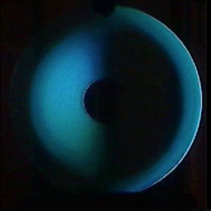
It represents all the trouble to run a Foucault test of a short focal length, even using the slitless. Imagine prepend a Couder mask and you understand how the shadow / light areas are indefinite.Now look at this other:
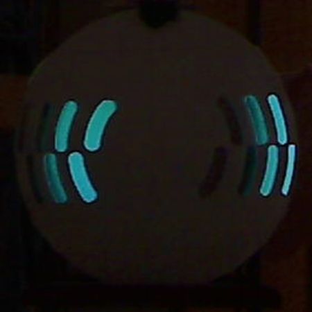
It has been achieved by putting the blade directly on the light source, exactly half of the LEDs slide.
It is seen as the boundary circumference shadow-light is well defined.
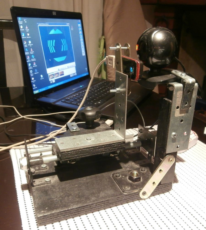
Intrigued by this result I changed the tester turning it into a Foucault “reverse” namely:-The source with the front blade are integral in a single block and slide on the guide in the longitudinal direction as in the slitless.
– the observer is fixed ( It is clearly the webcam to be fixed
 ) and no longer in front of the blade.
at this point I wondered what there were contraindications to use Foucault in this mode, given that there would be certain advantages in accuracy of readings, indeed:
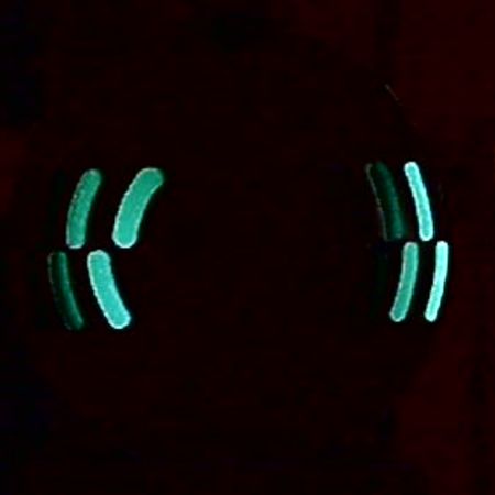
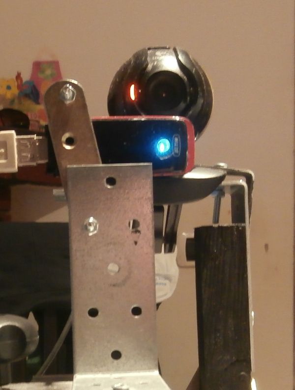
– being the boundary line light / well defined shadow, and considering that in a short focal we will never have a uniformly area “Grey”, I tried to perform the measurement when the line is perfectly in the center of the sectors of the area in question, which turned out to be fairly simple to do in this mode:
in this image the boundary line falls in the middle of the area 4.
another advantage: a shift of a few hundredths of mm alters this symmetry im visible way, You can also make images like this and make the measure “objective” also verifying the average distance in pixels of the line image on the same.
then we can also “to play” with webcam checks to emphasize this division to make even more comfortable reading:
Contraindications:
the only one I've found so far is the fact that the room must be perfectly still and not moving even have micrometric, since what is measured is the variation of the focal planes with respect to a reference that is the one where is positioned the webcam.So this test should be used as the classic Foucault ( without doubling the measures as in slitless ) with the difference that were exchanged moving parts scruple in fixed ones: in the classic tester fact is the source to be fixed and the blade moves, while observers can stand “where he wants”, here we have blade and source integral with and movable , while the observer is fixed on a focal plane.
I remember some time ago Mirco had suggested a similar system for the measurements of the shadows / light, I'd then have your opinion, If you think it is feasible or if there is any “trouble” which I escaped, and that should be solved.
 5 May 2015 at 19:22 #5846
Between these two images is a longitudinal displacement of 0,1 mm. I think the difference is perceptible.
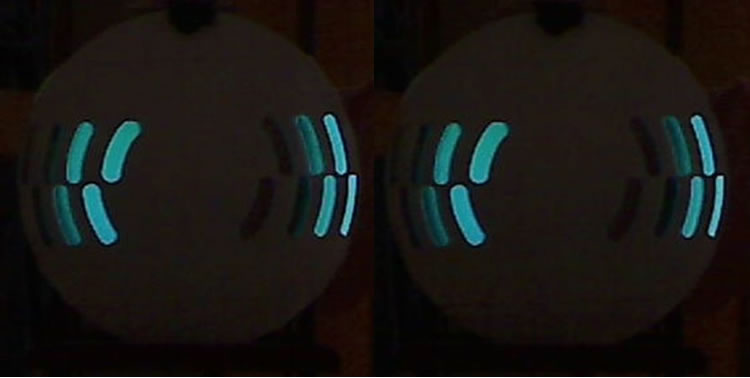
The “Announcements” compared to the classic tester it is that you must evaluate the exact spot where the shadow line passing through the center of the test areas in a symmetrical manner, and this can only happen when there is located exactly in the radius of curvature of the median area of the circumference ( that then you have to calculate in each case to bring the measures to it ).
8 May 2015 at 9:58 #5850I will have to pay compliments to the trick by which make sharper the contrast light / shadow, making it a very interesting method.

Technically and from my little experience, It does not seem to me that your solution can create problems, It is seen that the shadows includes the performance and behavior.The biggest problem, if anything, is to maintain in place the camera, but I also believe that making the evidence, those who practice them is alert and realizes if something goes doubts, and repeats.
Son also impressed by the sharpness of images taken, which they are much better than those directly visible to the eye! I'll have to learn to use your webcam too
 9 May 2015 at 1:51 #5860
Hi Massimo, very interesting what I read. Being able to have a line of much clearer separation between light and shadow is of great help in the measures, so this speech deserves to be deepened.
As you said also you do not seem to me that there are particular reasons why they say that in this way should not work, provided to maintain the lateral distance between source and sensor as small as possible (especially for a quick mirror as your, otherwise it introduces astigmatism in sizes).
Would you put the picture with more details of the set-up you are using?In your report, write that lasted the test of Foucault, given the low focal ratio of your mirror, the windows of the mask never take on a gray color "" uniform, but you have to evaluate when the light-shadow boundary is in the middle of the window. But at this point the windows you do not need anything, one would advise me to use a pin-stick mask similar to this one in which the vertices of the triangles will be positioned in correspondence with the average heights of the actual mask windows. So you'll have a better reference of where to drop the border of light and shade. I do not know if you can help ...
And, time ago I told you that I wanted to try to do the Foucault reversing those who usually consider the data set and measured. In foucault classic impose on us what the mirror rays go then to measure the focal (we do what constructing the mask). For each window (then for each of the same average height) we go to the center of curvature measured and then the draft with respect to the central zone.
data imposed: average height windows
measured data: draw the various windowsWhile I was thinking of imposing set of drawdowns (is. every 1,5 mm) and for each position to take a picture, from which to be able to extract the point at which there is a light shadow border, and then what we usually call "average height of the windows".
data imposed: drawdowns photos
measured data: average height of the light-shade boundaryTo give you a practical example, I analyzed the pictures you've taken the test:
I uploaded the photo to a simple little program I wrote in Visual Basic, and once I tell dev'è the center of the mirror, he automatically calculates me the light-shade boundary point.To do the first thing to calculate the brightness of the pixels along the horizontal diameter. In the first picture you see the pixel brightness profile which is also reported mirrored with respect to the center.
The point where the two curves intersect corresponds to the point where the 2 curves have the same brightness.
In the picture 2 It is shown an intermediate stage of the calculations, wherein the maximum vertex corresponds to the light-shade boundary.
In the third image is plotted, the desired circumference and is automatically calculated the value of the radius of the circumference. In the specific case is the 117,56 mm.Obviously the first 2 images do not need and are not plotted by little programs, that only the 3rd plymetal.
9 May 2015 at 11:40 #5863Good idea Mirco , the pin-stick is definitely worth trying !
The setup is usually with minor changes,a bit’ I improvised just because I had no clear idea of what I was doing…
Now the blade, or better the metal foil in contact with the LED has been replaced with a slit made with small strips of insulating tape attached above the slide (dish) the LED inside the key.
Is’ It was an operation of micro-surgery, but it seems to work fine, best of the lamina.
In fact, now I can see a roughness that was more evanescent , I can also start the shadow from either the right or left and use the same setup for the Ronchi ( in the video the reticle is held by hand )
)
THE problem I found is that the webcam should be calibrated, different adjustments can alter the visual perception of the shadow with respect to the light making the reading more uncertain.
with more settings “soft” It also sees the gray border area.
Your method is interesting, It should be tried and compared with the results of the readings made with foucault.
So far the readings that I did show some error, I simulated to verify the Ronchi graph with foucault readings and I compared it with the real rhonchi. If the readings are correct the two Ronchi must match. However, so far few differences I always found, Now I'll try thanks to your suggestion with pin-stick, let's see if I can improve the quality of the readings.9 May 2015 at 16:09 #5866Very interesting and certainly useful graphics processing Mirco, and very useful the use of webcam.
In conclusion, I feel just a “old iron”
 , but I can only be satisfied by the thought that you are teaching me many interesting things new. 12 May 2015 at 18:03 #5869
Maximum, I understand your attempt to improve the reading Foucault, which is actually something I've always tried to do me too, But as much as I tried, I always noticed differences between two successive measurements. This of course is normal, and until it is in an early stage of parabolizazzione or anyway it is not yet close to the final destination slight differences between the measures do not involve who knows what problem, but when you try to measure a surface that is very close to the parabola (or the reference conical), also enough differences 1 tenth of a millimeter to have appreciable differences in output results.
I personally have never been able to appreciate the differences between 2 placed in positions of the blade 1 tenth away. The content of "gray" in the window looks the same and I have to move at least 2 tenths to begin to appreciate the differences. And since my sensitivity in measurements is close to what I consider the minimum necessary to obtain good precision analysis is clear that even from a purely metrological this is not a good thing point of view.
This difficulty in identifying the precise focus of a window has always pushed me to groped with less subjective tests, and those who have always fascinated me is the interferometers. Usually these are not as easy to build or require expensive material (why I've never built one), but among all the models that I found to Bath it seems to be a good candidate to try.
From what I read it seems pretty easy to do and all components (except laser pointer) you can buy for about 40$ (plus delivery) in a well-known American surplus site.
However, due to the misalignment between the forward and return light beam (max 7-8 mm), this test inherently introduces astigmatism in the results and this contribution is greater the greater is the diameter of the mirror and the smaller is the focal ratio. This problem seems to affect the goodness of measurements, however, it is not frightening because there are 2 methods for groped to obviate this:the first (less accurate) going to remove from the analysis due contributions all'astigmantismo. Not doing so will actually discerns between astigmatism present in the mirror and the one introduced by the tester, but they exclude both of the results. If you are sure that the mirror surface is beautiful axial-symmetric is reasonable to think that the results are still accurate enough.
The second one (more precise, but more elaborate) It consists in carrying out the test several times by turning the mirror through 90 ° each time dates so that the software is able to discern the actually present astigmatism in the mirror (it will rotate with the same) and astigmatism introduced by the tester (that will always be oriented in the same direction).
I do not know you, but to me this very intriguing test (also because it scans the entire surface) and I hope to build one sooner or later ...
So to get this off worm that runs in my head now for a little while ... 12 May 2015 at 19:42 #5870
Agree on all ! Foucault personally I need to get a minimum of correction before using the caustic test, the difficulty is to get with the certainty of what is measured.
As you rightly pointed out, the problem is just to make the test less subjective especially in the delicate final phase. To this affect me your method which, I believe that it can be combined with Foucault to have a less subjective feedback of the measurements performed.
Each measurement contains errors, they are evaluation, the tester's accuracy or extra-axial aberrations not matter, what interests, as you say, you get to have a magnitude that expresses the magnitude of these errors, also because they are systematic and “dirty” the actual values consistently and in the same way in different sessions.
I thought you might:
– perform some sessions with Foucault / pin-stick and read the measurements ( a video con webcam ) , saving an image for each reading ( real or perceived ) the center of curvature zonal.
– with the same setup to perform measurements using your method , ie saving an image at every predetermined feed increment of the carriage.if the measures are exempt from errors the two resulting curves must coincide.
if instead, emerge differences, the extent of this variation could give us an idea of the magnitude committed and its location, assuming that the software is more “need” of us in reading the shadow outline.Moreover, thanks to your software, we can calculate images saved in the foucault, which radius of the area we actually went to read, Also this comparison should return an error measure compatible with that detected previously.
This cross-checking could provide help to the understanding and assessment of their systematic errors so that they can be put in the budget and used as “tara”, at the same time may provide useful elements to optimize your method even to the point of exclusive use.
As you say, the difference in gray after a small displacement is almost imperceptible, so I think to evaluate a picture is better evaluation “live”.
In this case, the errors may also depend on a good calibration of non webcam, that alters the perception of the actual intensity of midtones. The comparison with your method could also serve the development of the acquisition parameters of the image.As for the interferometric, I'm also fascinated me, despite my poor and inadequate preparation of this test. It would be interesting if you started experimenting with this method and study its “feasibility” even for us ordinary grattavetri.
25 October 2016 at 18:10 #8788Hi everyone,
I started to build the Foucault tester, and of course I would do the alternative.
There are information related to the building came out lately?
In a video on the construction of a tester, I saw that they used as a comparator I possess and that a hike of about 5 mm. But what must be able to slide the carriage back and forth?
The slit that makes pass the light of the LEDs should be as wide? And what must be high?
FrancoFranco
26 October 2016 at 0:06 #8790hello Frankq
As for the construction of a Foucault tester should you follow the pattern that has developed Massimar, described in an article of this Blog, and then possibly modify it as described by him in this same discussion.As for the excursion of the measurement that as a minimum must be able to fulfill the longitudinal carriage of the tester, it is the result of simple calculation hm ^ 2 / R that we will become family because it is the one that determines precisely the draw, ie the radius difference between the center of the mirror and the edge of the reference theoretical parabola for your coatruzione of the curve specchiio. Difference which is precisely the minimum excursion of the carriage of the tester.
Where hm is the radius of 200mm for example a mirror diameter 400mm; and where R is the radius of curvature of its spherical surface, knowing that the radius of curvature is twice the desired focal; and that the focal length of 1600mm has a 400F4, and then R is 3200mm.
Therefore hm ^ 2 / R = (200^2/3200)= 40000/3200)= 12,5mm.This tells you that the excursion of a comparator of only 5mm is not enough, and that you need is a little longer because of 12.5mm you need a little bit of the game can not practically start from scratch extent esattamentela.
You can elimijnare the problem of excursion thereby mounting in indiferentemente tester from an expensive micrometer, a simple threaded rod M6 (as I have always done) that the pace of a mm, and a hike, for example 50mm, and put on his head a wooden disc knob with pasted on its circumference of any measure, a paper tape as long as it and having 100 divisions, so we would read over the millimeter without going in difficult, and the penny is always sufficient.
The slit is long enough that it is 4 0 5 mm as the diameter of a Led which is the most common type 5mm as generally is the apple of the eye that even at our age the must see.
The opening of the slit is normally from 10 to 20 microns, that we put in the middle of a magnetic tape cassette and close the two halves against cli, then remove the tape.
A wider slit is less sensitive as a measure, at least at the correct perpendicularity that must be common to that of the movable blade, but it is more comfortable to the eye vision because they do not make a lot of diffraction fringes. But using a webcam the problem of nuisance fringes know that there is.He would agree to read some written here in grattavetro on Ronchi and Foucault test well to understand the function and utility, and learn to use them to predict the corrections have to do.
But you should also see the movie of John Dobson tutorial which I put an Italian translation to follow all the part where John “scratch” a 400F6 (…but it is a “easy” F6…) without neither the Ronchi test, nor the Foucault test but running the star test on an artificial star.
27 October 2016 at 7:45 #8797Ciao,
Practically I read and trawled items Grattavetro but I realize that, I become more wise It becomes more difficult to store the new information.
Question: For a mirror 300 F5 is a better Coudier mask 4 zone o 5?Franco
Franco
27 October 2016 at 10:42 #8798Better 7 or also 9

In theory, There are more areas, more we will be able to measure accurately the parable, while in practice most areas there are more testing becomes long and difficult. 27 October 2016 at 11:04 #8802The number of the Couder mask areas depends on the diameter of the mirror and its radius of curvature that is twice the focal length.
This is because the windows of the mask will gradually shrink in geometric progression, as it goes from the center toward the edge mirror, by reason of the fact that in that same way and sense the parable constantly increases the mirror surface radius of curvature.
But this change is the greater and more sudden the smaller the focal length of the mirror that becomes more "rounded", and to see the "spot color" without adding confusion to the already difficult to detect it, it is necessary that the windows are in the closest possible (ie are in greater numbers) the more the focus is short, because the radius of curvature changes rapidly and becomes increasingly difficult until impossibilitare to identify "the spot" watching from the distance meter that is on the bending radius.
Jean Texereau to maintain good visibility of eye shadows (but he did not use the web-cam) recommended not to go below the width of 15mm 2 windows of the outermost zone.
I've used for my 300F5 6 zone e 5 on the 250, e 7 on the 360.
A formula that calculates you in geometric progression, zone by zone, the outer radii of each of them to be cut on the mask couder , it's the following:
Outer radius of each zone Hx = Radius mirror * root (number area / many areas)
27 October 2016 at 13:31 #8803Ciao
I've used for my 300F5 6 zone e 5 on the 250, e 7 on the 360.
Mask with 6 zones
a simple threaded rod M6 (as I have always done) that the pace of a mm
Massimo though it used M10 that has a step 1,5 mm, each division is worth 0,015 mm
Why?Franco
27 October 2016 at 14:06 #8804The purpose of the Foucault test is to read the longitudinal displacement to the hundredth of a millimeter.
If you use a M6 threaded rod that way 1, to read 1/100 mm have to paste on the circumference of the disc that will be the knob of the screw, a strip of paper with 100 divisions of same circumference.
If you are using a threaded rod with a pitch 1,5 to read a 1/100 mm strip of paper that must have 150 divisions.
-
AuthorPosts
- You must be logged in to reply to this topic.