To obtain good interference fringes, for the control of optical surfaces, through the so-called "test plate", It is necessary to have a 'apparatus allowing to uniformly illuminate, with a monochromatic light, the two glasses under test and redirect the resulting image at the device or towards the observer.
The device itself is quite simple to implement, because, as you can see in the image below it is made, by a supporting structure and external protective, by a source of monochromatic light, a diffuser and a semi-reflective glass placed at 45 ° to reflect toward the outside the image of the fringes produced.
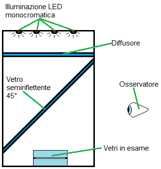
Fig. 1 – General diagram interferometer Newton
The interferometer shown in Figures, size is 220x200x300 mm and the structure was created by setting a series of wooden rods by 10×10 mm. Then, they were fixed on the structure, the "C" shaped plastic rods (on di 'U') of 5×5 mm, which will act as guides on which slide into position the two real. In the photos below it is also highlighted the small M3 screw which acts as a retainer, to prevent the slipping of the glass tilted.
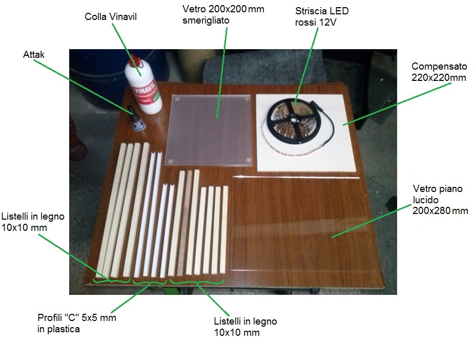
Fig. 2 – Component Diagram


As regards to lighting, to the present day, It is simple enough to have a monochromatic light, just use LED bulbs.
In the project described on this page, it used a red led Strip 5 metri a 12V (4.99 € your internet) which has been cut off and stuck on a plywood rectangle of 200×220 mm, and arranged on 9 parallel rows such as to cover in fairly evenly throughout the available surface.
These strips can be cut roughly every 4-5 cm along the appropriate signs and assembled by connecting the respective terminals of + e -, as shown in Figures.


The light emitted by LEDs must be arrive to optics as if it were emitted by a single surface of brightness and constant intensity, for this we must interpose, just below the LEDs a diffuser. This was been achieved by grinding with carborundum grit 80 (or alternatively 120) the surface of a glass, that once satin will light evenly spreading further.
It may happen, however, that although it has frosted surface of the glass to produce a light as uniform as possible, This does not happen at all, and remain clearly visible areas much brighter than the other right just in correspondence of the overlying LEDs. To remedy this,, or you will grind the glass surface with a coarser grain, or also you decide to grind the other face of the glazing, or you can add one or more states, depending on your need, sheets of oven paper that well intervene to solve the problem.


To reflect towards the outside the image of the interference fringes is necessary to place a half-mirror placed at 45 ° glass in a way which allows the passage of the monochromatic light from the light source towards the mirrors in the examination, but which then reflects the returning light from them towards the observer.
As an alternative to semi-reflective glass, you can use a common polished glass, which equally will allow the correct operation of the device, at the expense of a lower brightness of the resulting image and a sharp decrease in the contrast of the fringes.
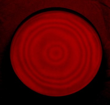
And here is an example of Newton's rings that may occur during the test:
While the following are more photos of the assembled and operating device:


Once you have assembled the all, you can cover the entire lateral surface with cardboard, or black plastic, to improve vision and contrast of the image, with the obviious exception of the side facing the observer.
In the following article instead: Fringes of Newton-Concavity and convexity of the surfaces under examination They show the basics for the interpretation of the classic forms of interference fringes.