Is’ born in 1939 and it serves to measure with extreme precision (impossible to Foucault test for reasons which we shall see here later looking at the title: REASONS WHY THE FOUCAULT TEST IS INACCURATE FOR LOW FOCALS RATIOS MIRRORS)) the radii of curvature of the zones of a parabolic mirror, or even more deformed figure from, a very short focal ratio (that is more inferior to F5) and a beyond the diameter 300 o 400mm, to guide its perfect optical correction in construction phases.
Is’ a test more “spartan”, ancient, less demanding and less costly in terms of photographic hardware needed for the Hartmann test 1960, and it is therefore more accessible for use amateur.
Even the test Roddier (described in another article of this blog), It is subject to the same complications hardware Hartmann, but has the capital disadvantage that be useful only to provide a qualitative assessment of precise optics already terminated. And therefore it is not usable for the purpose of driving at the maximum correction required in the manufacture of a new mirror.
The treatment of the caustic test is designed by nature to a small circle of very specific amateurs. Not for nothing it appeared (from the 1935 to date) worldwide in a few documents, two of which are the following:
- The text from the book “Amateur Telescope Making”, volume 1 (mine is the second edition of 1998), with an article, course in English, posted by Irvin Schroader from’ Applied physics laboratory della Johns Hopkins University (Baltimore – Maryland – USA);
- and in a special section contained in the excellent French book entitled “Realize your telescope”, di Jean Marc Lecleire (My issue which is of 1997-1998).
Both of these sources are available in the languages of the countries of origin, where the amateur optical Do it yourself was (at the end of last century, in the time of my studies from amateur “grattavetro”… But perhaps it is true today), certainly more widespread in Italy, where therefore, an italian tutorial on Caustic testing is still, Remote 17 years, not available (even for the genius of the Italian “of maximum entropy”, that is to choose the “more natural and less fatiguing to postpone”, opting to purchase the “more expensive” because did from others, that is mistakenly perceived as better).
therefore, being I curious and “insider”, as a result of my first shy and not thorough practical approach (excluding “aid” of dubious quality from the Forum, and in favor of the classical, reading of authoritative books) remember I translated into Italian a summary of the technical concepts that define it, as my initial operational guidance immediately accessible.
Of course immediately accessible for my own use, and use of those few Telescope makers like me that do not disdain the active involvement , and that perhaps will reap some benefits.
The tester for lead a caustic test is a more complex variant of the Foucault tester, necessitating respect to this, a precise and micrometric measurability ALSO on orthogonal axis (Y diametral mirror axis), in addition to the precise longitudinal measurability along the optical axis (X) mirror.
Practically, While in foucault test the operator localize the center of the radius of curvature of a certain annulus of the mirror, that is reached when he sees appear a "flat shadow" simultaneously in pairs of diameter Windows on Couder mask, What evaluate as "flat grey" , In the caustic test, vice versa for the reasons we will see, He must, in first time, calculate most accurately X coordinate of every pair of windows representing each mirror zone concerned, and then had to measure the Y coordinates that are the mutual distance between these two windows.
The feature lets say ... " QUEEN " of this test is that the caustic is NOT’ a SUBJECTIVE test, As inherently the Foucault test is, by the fact that the operator should not as in Foucault judging by eye shadow equality of two diametral Windows; BUT must rather find the caustic image of the slit, in one window at a time of the two, for each zone.
The useful image of this caustic slit looks so incontrovertible as a strong clear line on Milky background.
I could say that it is not in fact the real image of the slit, but the complex of the absence of diffraction lines that characterize in that only one focal point, where is shown clear-cut and clean as a bright vertical line, such as that represented in figure.
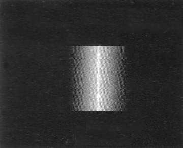
Fig.1 – Caustic of the slit focus (is not the image of the slit al focus)
Image Clearly distinguishable from that no longer clear but blurred, that the slit would show from himself when he was caught with the tester in a still position intrafocus.
Or conversely when it was caught in a position extrafocus, presenting gradually broadside interference fringes, up to divide and double itself.
The caustic test is born from a study in 1939 that the two Argentinian astronomers and physicists Richard Platzeck and Enrique Gaviola, They published in the Journal of the Optical Society of America.
This test have as authoritative “baptism” the prestigiuos construction began in 1936 of the futuristic Hale telescope installed at the observatory of the Mount Palomar (San Diego, California) managed by "CalTech".
That is a Cassegrain telescope with a diameter 5,08 m and focal ratio F3,38, getting first light in 1948 and remained the largest telescope in the world until 1976.
The mirror weighing about 14 tons was achieved by melting the new brand "Pyrex glass" with low thermal expansion, patented in 1919 by Corning Glass US. Never previously melted into this big single mole that present risks of brittle fracture for cooling of inhomogeneous big glassy mass.
The grinding work for the curve excavation lasted 13 years with the removal by abrasion, the well 5 tons of glass, necessary to achieve the desired depth of slightly less than 100mm of arrow.
REASONS WHY THE FOUCAULT TEST IS INACCURATE FOR LOW FOCALS RATIOS MIRRORS
Recalling for newcomers that the construction of a parabolic mirror always starts with the easier realization of a spherical surface, whose reflected light but does not lead to converge in a single focal point for all the rays coming from an object at infinity, as it is necessary to fulfill The telescopic function. Therefore the focus image is unusable because it looks like a patch formed by the superposition of an infinite number of non-overlapping images.
To build a reflector telescope objective needs that the spherical surface of the mirror is then processed and distorted "countersink" in the form of a parabola, which differs from the spherical shape to not possess a single radius of curvature of the surface, but owning one that increases in a progressive and continuous manner, According to the mathematical formula that defines a perfect theoretical parable keep as reference, with a radius, which is minimum at the center of the mirror, and maxima at the edge.
Such a continuously increasing radius allows to focus and form the image of the object to infinity in one focal point. Very small image that will be observed with eyepieces that let you enlarge a number of times equal to the ratio between the focal length of the mirror and that of the eyepiece .
In the practice of realization of a parabolic mirror, the precise measurement of the gradual and continuous curvature of a parabola rays, It was and is, impossible if we non resort to an compromise simplifying expedient by splitting the mirror in circular crowns much more restricted as we proceed towards its edge where the change in RADIUS is more abrupt.
In Foucault test, to assess what are the extent of that their radius of curvature, is assumed that each of those fictitious circular crowns have a "Common radius", that is, as if that limited width glass ring, had spherical surface.
In that then tests, the finding of the radius length occurs when at some point longitudinal movement (draft) Carriage tester, the introduction of the knife edge in the cone of light reflected, It appears to the eye of the operator (simultaneously in both Windows of Couder mask opened on diameter that identifies the Crown) the "flat grey" of the shadow.
The flat grey come only when the shadow is perceived not coming from the right nor from the left, but as the closing of a diaphragm on 360 degrees. This phenomenon occurs only when you are “more or less” in the center of curvature of the fictitious zone, that is, when you find yourself with the blade of the tester at a distance equal to the radius of curvature of the mirror, radius that “we assume common” for that surface under examination.
In considering those annuli having common radius, we makes a subjective mistake or error that is much more insignificant and less damaging as the mirror has a little deformed parable, that is little different from the sphere, that come when you have a long focal lenght (from F5 – F6 to rise).
But in examining the shortest focal as F5 that subjective error becomes quickly too big, beginning to be measurable by mirror diameters greater than 300mm, and it is becoming more and more important and damaging way, because the center of curvature of the short focal length parabolas rays fall only optical axis for the central zone, while (as we shall see in the next chapter) for the other zones they fall on a caustic curve that moves away more and more from the optical axis, as you reach the edge of the mirror, most obviously damaging the quality of the mirror as a function of the increase of its diameter.
For those low focal lenghts, the caustic test method is instead better and decisive, as already mentioned, We not more subjectively assesses by eye the quality of a shadow that appears simultaneously on the two diametral Windows, but in each crown circle, we take in consideration the clear caustic image produced by one window at a time, pre calculating the coordinates X, and going on that coordinates to measure coordinatesY, of mutual distance from the two Windows.
With the detection of the coordinates X e Y, of each zone, the measuring method of "caustic" is all the more accurate as is greater the longitudinal aberration at the center of curvature (the term aberration means the deformation compared to a sphere). Characteristic of the short focal lenghts i.e. deep parables or hyperbolas.
For this reason the caustic test is a test not applicable to spherical mirrors or parabolic having medium or long focal lenght, that is, when it have little deformation than the sphere, because the X and Y coordinates would be so small as not to be measurable, because were confused with the same sphere. Therefore, caustic test is of impossible application at the end of polishing when you start parabolizing a surface that now is yet only speroidal .
It is usually recommended to start and maintain the measurements with Foucault test, until the mirror does not come to possess a parabolic shape with precision very close to lambda / 4 (maximum peak / valley on the glass error equal to 68,75 millionths of a millimeter).
But at that point processing (which normally characterizes the attainment of the minimum quality “entry level” lambda / 4 for one of the focal mirror equal to or greater than F5), the short focal length mirror lambda / 4 with the resulting Foucault is NOT yet finished.
It then starts only from that result onwards, to apply profitably the caustic test, that will lead to the precise subsequent corrections until the end of the mirror flawless workmanship.
Contenting ourself or continue further with the inadequacy of the Foucault test on short focals, it means estimate millionths of a millimeter guessing, instead of measuring and be guided to realize the actual curvature of the mirror, and is a short cut or a malpractice very unprofessional, that can perhaps satisfy their “Do-it-yourself” for a visual use of the telescope, but whose poor optical quality you can find out by subjecting the mirror to a qualitative deep testing , as you are obtained for instance with the Roddier test described in a separate article, even here in Grattavetro.
Is’ It is known that Newton telescopes with a large diameter and short focal length were born to have ease of access to the eyepiece without having to use a ladder, and since the large mirror diameters favor the vision at the highest magnification of small parts on the surface of the planets, or the separation of stars very near double, the poor quality of the primary mirror made with Foucault test is also perceived at first with suspicion, and further with certainty from the eye dell'astrofilo smaliziato, and then usually it confirmed by deeper qualitative tests.
And saw that the tendency of wishes of amateurs astronomers and technology go in the direction of large primary mirror diameters, and so comfortable short focal lenghts, it is good that those who want to order a mirror is sincere that the mirror is not made with only the Foucault test, to avoid incurring sooner or later at that initial suspicion that arises with the use of the telescope, and that is often confirmed by extensive testing. And having regard to the apparent diffusion of short focal length and poor quality mirrors, this is the reason why many savvy amateurs who do not like them, preferring to use the same old ladder.
THE OPERATION OF THE TEST OF CAUSTIC, and because it is better than the Foucault test.
There help observing some figures:
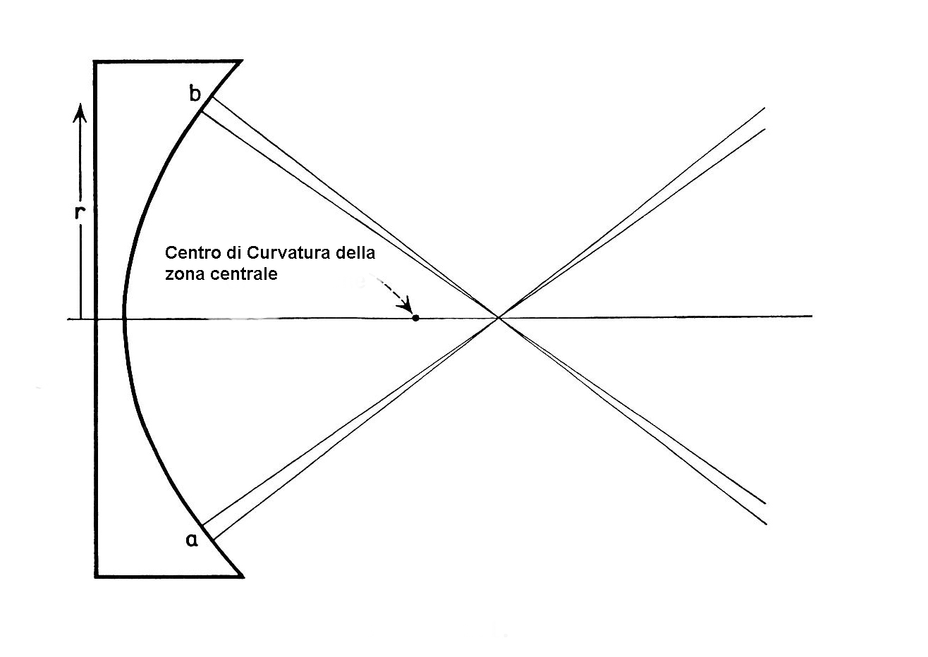
Fig.2 – The arrow show the center of curvature central zone
Looking at this image that refers to the reflection from an arbitrary circular crown containing a and b windows on a parabolic mirror surface, we find depicted the two theoretical assumptions underlying the Foucault test; and that are:
- For the named practical reasons by measurement, is considered spherical (i.e. mono RADIUS) every little surface zone (including the annulus containing our arbitrary surfaces "a" and "b", regardless of the fact that in reality the surface of the mirror is parabolic or even greater deformation).
- It is believed that the reflections of each annulus (circular crown) fall "always" on the optical axis of the mirror; Then the reflection from the center mirror falls at the point arrowed figure as "the center of curvature of the central zone", that is the true, But it also reflects the product from the area that contains the "a" and "b" windows is considered to fall on the same axis, and what instead is not it.
Or better, It has been demonstrated that this is negligibly very close to true only for long focal lengths, but it is not for the low focal ratios owned by very warped mirrors, Since bringing in "flat spot" with the Foucault test the two windows enough peripheral "a" and "b", and then removing the mask Couder, you will notice that the shadow actually flat of the knife edge, first shown through the windows, instead is moving according with blade movement, proving that We are NOT in the perfect Centre of curvature, but there We still are in intrafocus position.
Also here We will help the next image:
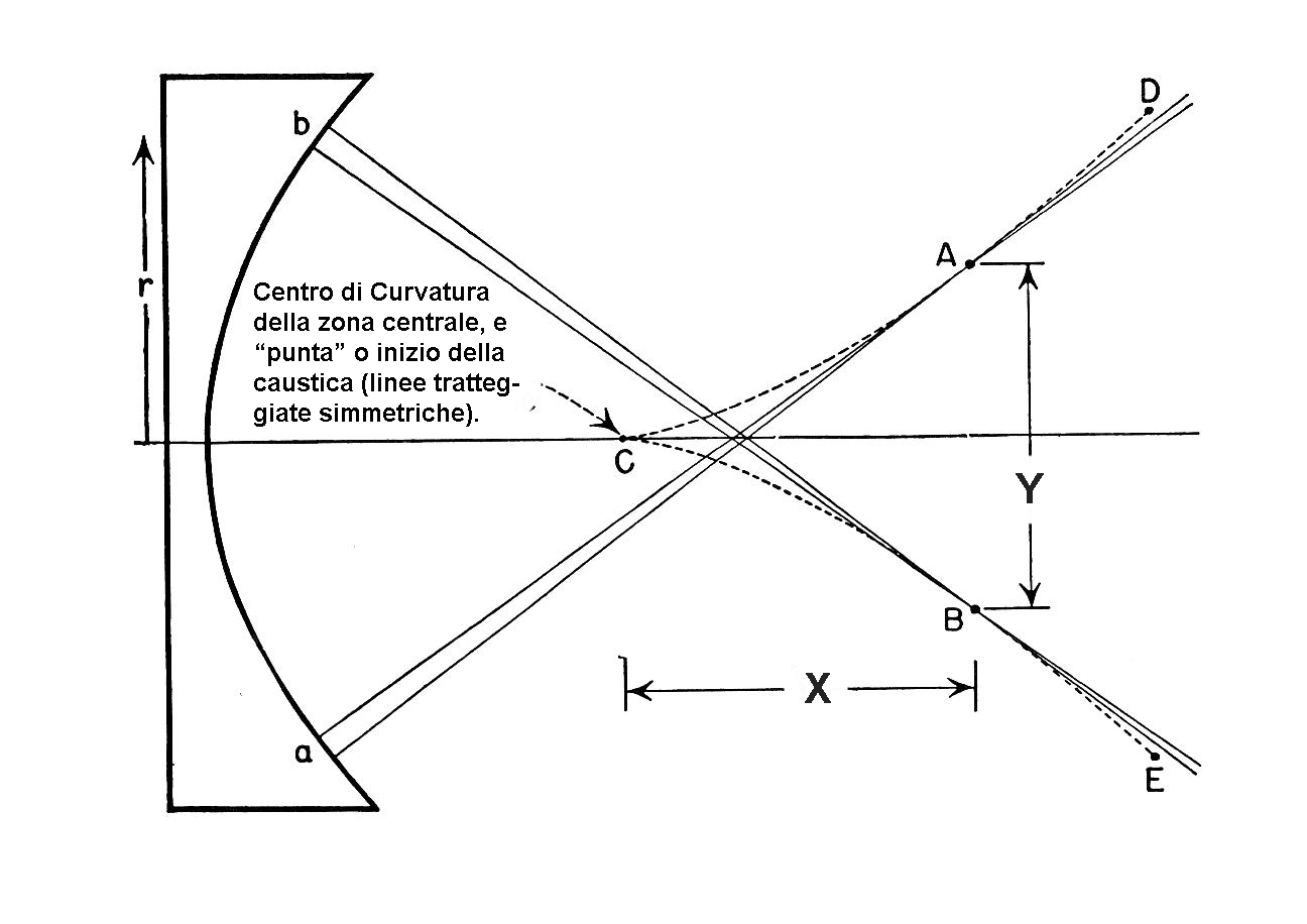
Fig. 2b – The caustic path of the relfections
The study of Platzeck e gaviola was tense to realize a method to measure the exact position of the actual focus reflected by each zone (including our hypothetical areas "until " and "b”). Finding that for them the center of curvature does not fall on the optical axis where the two reflected are crossing it, but it falls in points A e B which are located in a precise and pre-calculated distance X from the point -, where it falls only the reflection of the central zone of the mirror and the seat of the so-calledtip of the caustic, in others words, it begin the caustic curve dashed in the image, and those two reflexes are separated radially by a distance Y.
The distances X and of Y, from the optical axis, as shown by the dotted curve, they have much more proceeding towards the mirror's edge, as much as it has short focal.
And these points, for the various zones, all lie progressively along the dotted curve-shaped pavilion trumpet indicated the image above, which begins on the optical axis solo to the point -, where it falls only a reflection of the central zone of the mirror.
PREPARING THE THEORY TEST
This is to acknowledge that need to measure very accurately (at least hundredth of a millimeter), the coordinates X e Y, the Centre of curvature of each zone.
Referring to the following image (obviously in exaggerated scale for reasons of understandability of the phenomenon) we enter the principle of the test, and we see that a light source formed by a slit, It is installed to the center of curvature of the central zone - of a parabolic mirror, and illuminates the two small regions a and b, positioned to "height" h from the central axis of the mirror surface.
(In opticals tests, man use optical slits instead a pinhole, because much easier to achieve. There is talk, for example, wide 20 or 30 microns, where the implementation of a pinhole of that diameter is much harder, While presenting both the hole and slit, the same physical properties, with a remarkable and convenient advantage for greater visibility of the latter)

Fig. 3 – Curvature centers on Caustic path
Platzeck and Gaviola experimentally found that the image of the slit was not observable in P, as assumed by the Foucault test, but it was necessary to move further into position gradually off-axis, and lying on points which construct the two dotted lines describing the bell curve. In our case the precise focus point of Windows a and b is located A e B symmetrical to the optical axis, but not lying on it.
All of the surface of the parabolic mirror obey this rule, except the first point on the central zone of the mirror, which it is the only one to fall into - on the optical axis.
It was determined that for the purposes of accurate measurement and the resulting chariot displacements and focal readings, affecting “young mirror maker ” alias "grattavetro", is called X the distance on the optical axis (in the figure it is horizontal) between the end -, (where is the "cautic tip" beginning of caustic curve), and the projection of the points on the optical axis A e B of each zone to be measured.
Just as it is called Y, the distance (which in the drawing is vertical) that separates the points A e B.
With the following two formulas are then beforehand calculated the theoretical values of coordinates X e Y, possessed by a perfect reference parable, that is used as comparison and guide the realization of our mirror:
Where R is the radius of curvature of the central area of the mirror, e H is the height on the vertical axis of the zone measured.
If the tester was constructively type with the fixed source, that is independent of the longitudinal carriage movement (on which therefore the source NOT moves along the longitudinal axis during the measurements), should multiply 2 values X e Y, obtained.
CHARACTERISTICS TESTER
The tester retains the longitudinal carriage of the Foucault tester, but presents a new orthogonal sled, replacing the tilting that for the Foucault bore the lama.La new sled will support an eyepiece, for example 9mm focal, having vertical lattice or cross, which orientation should be aligned to the slit
The eyepiece serves to magnify the caustic of the slit image formed in each focal zone by the mirror, in order to better appreciate the exact sharpness and posizione.L'ingrandimento it is given by:
Magnification = 1000 /(4f) = 1000/(4×9)= 1000/36 = 28 times
In our example the eyepiece (of which f represents the focal) magnifies 28 times.
The side shift carriage must be equipped with a micrometric screw or a precision comparator with micron readability, or in defect, at least ten microns (hundredth of a millimetre).
We then creates a screen (a mask) in hard circular bristol board or plywood, provided with many pairs of round holes, drilled on diameter,what are the zones to be measured, leaving a space of separation of 2 mm between adjacent holes. Screen that will be placed vertically in front of the mirror,
The diameter of the holes is provided in approximately one hundredth of the radius R of curvature of the central area of the mirror: For a mirror with R=1800mm the diameter is then approximately 18 mm, but its real value is not critical,and will be determined more precisely by the optimal division of the zones in which it will be possible to divide equally the diameter of the mirror.
The number of holes must obviously be integer, even, and distributed equally on the two halves of the mirror diameter, with the outer zone tangent the outer edge.
In the case of a mirror with perforated center, the two innermost Windows is recommended that are spaced by a few mm from the hole, to not have a measurability disturbed by a spurious and extraneous light reflection coming from the edge of the hole.
After making the mask you make numbered little doors intended to close the Windows that are not in use, and fixed above the holes with adhesive tape, and closed or open at the slightest touch with a label like "post-it" adhesive paper, so it can be easily and most delicately closed or opened without the SLIGHTEST MOVE mask and mirror on its support.
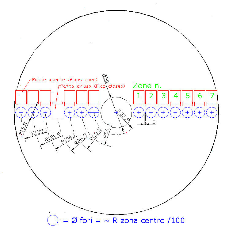
Fig. 4 – Mirror mask diameter 300 mm
The following is the only practical example traceable in the literature, of test conduction, It is located in the Lecleire volume above mentioned .
It concerns a mirror diameter 300 mm with 7 pairs of Windows, each diameter 15.8 mm. (amplitude ratio = 1/114 R) with spacing between holes of 2 mm
The "Hm" rays of different zones are shown in the picture 4
PRACTICE TEST OF CAUSTIC, ADJUSTMENTS:
After installing the mirror on her without screen support, it is necessary to place the tester to the center of curvature and turn on the light source. The return image produced by the caustic of the slit reflected from the mirror must project itself inside the eyepiece.
You act so adjusting screws the mirror support to center the image height of the slit within the eyepiece.
The width of a slit useful is shown in about 20 or 30 microns. The eyepiece reticle must be parallel to it.
Then proceed to the longitudinal axis alignment of the tester with the optical axis of the mirror, creating and putting in front of the mirror a new circular screen of equal diameter and equipped with three holes aligned on its diameter: One of the center and the other at opposite edges.

Fig. 5 -Mask for alignment on longitudinal axis
Fixed the screen in front of the mirror you will look at eyepiece three different pictures of the slit, each coming from a hole in the mask. By moving the carriage of the tester along the optical axis, it is noted that lateral images they approach or move away from the central, depending on the direction of displacement.
At the point of intersection of the two light beams reflected from the peripheral zones with the optical axis, the lateral images go mingling and overlapping with the central image. Then again they return to split, if you continue with longitudinal displacement of the tester cart.
You need to look for, If it is found that the central image shifts sideways, necessary to correct the orientation of the entire tester, both longitudinally and also centering better the orthogonal cart.
When the eye is aligned with the optical axis of the mirror, in any position moves the two longitudinal carriage, You see opposite images moving symmetric (at left and right of the eyepiece graticule) It materialized on the optical axis from the central image that remains perfectly stops.
For a better understanding of the test, removed the alignment mask, and replaced with the measuring mask with holes of the zones, in the two documents referred to above is made to the next image.

Fig. 6 – Slits image a end b, with centreline (clic on to see complete)
The figure shows, right-to-left, n. 13 photos of the slit coming from windows a and b, like in picture 3, moving the tester taken along the optical axis of the mirror.
The photo 1 It is performed at the point -, to the central area of the center of curvature: The image of the slit is double and blurry because we are in sincerely intrafocus position compared to Windows a and b, which are open on a peripheral zone.
The photo 6 It is performed at the point P on the optical axis: The two slits are almost overlapping but still out of focus. This would be the point where Foucault test would provide us the spot locating a "flat grey" shadow of the center of curvature.
But the real focus and clarity of caustic slit shape, found only in photo taken in position. 9, with the looks seen at the eyepiece:
Fig 7 – Caustic of the slit focus (is not the image of the slit al focus)
The image is found at that location away, moving the cart side of the tester. Going beyond that point will return the images to move away and go to extrafocal.
THE MOST 'IMPORTANT ADJUSTMENT
It consists in identifying the exact starting point of Caustic from which measurements, tracking the image of the slit SHARP as seen in above picture, in the position of the point - shape 3 corresponding to the first zone reflex.
Since all subsequent measurements depend on that value, it is necessary that it is identified with the utmost precision (at least 2 or 3 cents mm).
MEASURES
- We have anticipated that you will need to calculate in advance the theoretical values of X and of Y, With the formulas X = 3h^2/2R e Y = 2h^3/R^2, .
- On each calculated value X you add the initial value read on the micrometer screw at point C caustic start, getting the value X correct. (E 'the reference value of all the measures, and for this, is very important its maximum precision).
- Then open only the left side hoel window in zone 1.
- Moving the tester on the theoretical value X calculated for this corresponding zone.
- Centering with care the eyepiece reticle on the image of the slit to note the value Y, left (Ysx) read on the vernier scale of the lateral displacement screw-
- Without moving nor tester and neither mirror, close the left window and open the right one.
- re-center the image of the slit on the reticle only by acting on the lateral displacement, note the value Ydx read the micrometer screw.
Repeat for all zones, knowing that starting from zones tall approx. 0.4 times the diameter, usually can be opened simultaneously on both the Windows because the two images from that position onwards following the curvature to trumpet, will be more spaced out each other, and no longer interfering to overlap.
INTERPRETATION OF MEASURES
The purpose of the measures is to verify if, and where it is necessary to step in with fixes that removes any excess glass, to ensure that the mirror meets the following criteria which are interdependent and indispensable:
1) Lord Raileigh criteria (for extension of its physical concept expressed on the wave) established that the maximum size of a defect on an optical surface, able to begin to bring damage to the diffraction image, or Airy radius, It has the measure of one-eighth of the wavelength (Lambda) the yellow-green light to which the human eye is more sensitive, since during the reflection wave it will be damaged twice, one in incidence and once in reflection, bringing the overall damage to the value of (1/8 +1/8 = ¼) = Lambda/4.
Such a defect causes the loss of brightness at the center of the diffraction image, to disperse it in the adjacent rings, "widening" the bright spot in a "stain", with deterioration of overall contrast.
In our case it occurs visually on a special chart, what are the points at which to intervene with corrections, so that the broken line that represents the trend of the reflection of the areas of our mirror, It is as close as possible to the reference values parable, with a maximum allowable gap that must not be greater precisely to Lambda / 4
2) Couder requires that the light rays reflected from all zones of our parable converge inside the Airy beam said, that is, the formation of image disc. In other words, It is important that all zones of our parable participate in formation of diffraction image, as if one or more zones reflect their share of light outside of the geometric RADIUS, the image provided by the telescope would not have the canonical form considered by Lord Raileigh, with the deterioration of the overall contrast indicated in the previous point.
In our case it occurs on another graph visually appropriate, which zone possibly reflect out of range of Airy, able to correct for making them fit within the same.
That said, There is attrezza for measurements preparing a sheet with columns destined to receive the values of X and of Y, theoretical, as well as the values of Ydx e Ysx measured.
Write down how Ym the difference between Ydx e Ysx for each zone of the screen;
Finally, to calculate the "Reduced" corresponding to those raw measurements, using the following formula:
Measures Reduced = (Y-In) R/2hm
Where R = Radius of curvature at the center of the mirror, and hm = average height of each zone.
From these measures are calculated Reduced aberrations:
Longitudinal aberration to the bending center Alc; e
Cross focus aberration Atf
using the same formulas used for the Foucault test, which are as follows:
Alc = Measures Reduced - K
Atf = Alc • hm/2R
Where K is a positive or negative constant obtainable for subsequent tests, that must be selected in such a way that the Atf value of each zone, divided by the diffraction radius Airy of the mirror, give a value that is less than one (which in practice means that if this happens, the incident light beam is reflected to a focal distance inside the small radius of Airy).
Note clarifying the role of the constant K., and the result of its use, obtained with a single glance on a graph
In the same way it works by performing a Foucault test, Even with the Caustic test, pto verify the deviation of the raw parabolic curve we are constructing with respect to the theoretical one taken as a constructive reference, we have to imagine “overlapping” the two curves.
The overlap is used to be able to see where they are, and how wide they are, the protrusions of error that differentiate our curve from the reference one, so that we can correct ours with appropriate tweaks.
But a material overlap is not possible with our two objects which are only numerical, but it is it is therefore possible to superimpose them with a mathematical simulation.
The spreadsheet will then calculate a constant K for each zone. and we will therefore have at our disposal as many constants K as there are test zones in which the curve is divided, and we can therefore mathematically overlap, the two curves, zone by zone, one at a time, taking a different zone as a point of contact from time to time. Contact which in the spreadsheet is simulated by subtracting from all the other zones the value of the constant K of the zone currently being examined.
All the operation does require you to choose the values of one constant k at a time in the spreadsheet and look at the graph resulting from the new trend of the curve at a glance. And therefore choose which zone to use as a convenient contact point , based on our experience, ar work time, or to our ability and to the minimum amount of glass to be removed, to create a perfect parable, identical to the reference one.
Who is interested in seeing such an example simulation with the graphs commented to illustrate the pros and cons, I suggest you read this short article:
https://www.grattavetro.it/200f6-studio-sul-1-test-di-foucault/
End of note on constant K.
A WORD ABOUT RAY DIFFRACTION NOTCH,
That, also known as Airy disc, or radius of Airy, It is calculated using the known formula:
Airy radius = 1.22 * lambda [in micron] * (f/ D)
Where lambda is the usual wavelength of yellow-green light which the eye is more sensitive (550 nanometers high., or 0.56 microns); and f is the focal length of the mirror and its diameter D (in practice f / D is the focal ratio F, which expresses the opening of the mirror).
Airy beam for any diameter of mirror having F5 focal ratio is therefore:
1.22 * 0.56 * 5 = 3.41 microns
So in order to satisfy the criterion of Couder, the value of Cross focus Aberration Atf It must be less than unity, as a Atf = 1 would indicate the reflection of the notch on the edge, and a greater number of 1 indicate the fall out of this (also discoverable with the location of that zone outside the “"trumpet bell"” of the tolerances).
In fact if the result is for one or more zones over the unit, It would be necessary to touch-up because the mirror would not be of good quality.
The type of retouching to be implemented can be deduced from the graph transverse aberration Atf , and the amount of glass to be removed can be deduced from the graph with a broken which reproduces the wave profile. Both are the result of the (standard) program or spreadsheet used for the evaluation of the test.
At the end of each touch-up you need to recalculate the RADIUS R of the central zone, and all the theoretical values of X and Y different zones, before starting a new test of just corrected surface.
Note that if an Y measured is greater than the calculated Y, the zone of the mirror is already too deep (Alc is negative) and since the "Mirror Maker" can only take away the glass and not add glass where it fails, to enhance (rise) that zone will be necessary to lower the whole remaining mirror surface, deleting the currently executed parabolization, to return a little toward the spherical shape, so you can start over by it a new retry of parabolization.
Vice versa if a Y measured is less than Y calculated, the zone of the mirror is too high (Alc positive) to indicate a climbing zone that with a touch-up may be lowered (removing glass).
It goes without saying that approaching with our touch-up to that perfect parable of reference, It decreases gradually a few millionths of a millimeter (nanometers high.), the amount of glass to be removed in the past corrections, and therefore increases exponentially the risk of "remove too much", and then having to make a "game over" that forces the return back toward the sphere, deleting the last job done, to run a new attempt at parabolization.
It is worth mentioning that in these circumstances the amount of glass in the game, are of the order of millionths of a millimetre, and so there is no danger of ruining your mirror in return back a few dozen of they for try a new parabolization. The problem is at most only that patience that you have to put into play… to accomplish one definitely exceptional mirror, not contenting for a mirror of quality higher than the commercial ... but not amazing.
CONTROL REPORT
It 'a table grouping all the data we wrote, showing two graphs of interest for the provision of corrections.
It shows the theoretical values of X and Y; the practical values obtained for Y and the difference Ym; as well as longitudinal and transverse dimensions of aberrations Alc Atf mirror; inclines in terms of value and as a sign, so will allow to draw a graph with the reflected wave profile and to determine the accuracy reflected wave belonging to our mirror (the famous Lambda / n);
The following is an example of a control report on spreadsheet:

PROS AND CONS OF THIS TEST
PRO:
- It's a method considered impersonal because the will of the viewer interferes very little
- The measures are exempt from troublesome diffraction phenomena in the control window borders
CONS:
- Difficult search of caustic START in center zone, and the main source of error.
- The completion of the test takes longer than Foucault test
- The tester should have a high mechanical accuracy and without backlash parts.
- The test does not provide data on the whole surface, Neither finds an edge flattened or raised, and defects of size less than the size of the windows (such as roughness) They are not perceived.
IN CONCLUSION
The usefulness of this widely recognized test, It could definitely be comforted and enriched with practical suggestions on its run, which can only come from its use in the practice of making a mirror with a diameter over 300mm and a short focal length, of unsatisfactory realization with Foucault.
This mine, it is only a very superficial cognitive approach. So I hope that a completion of suggestions can come from anyone who put the test, on testing practice.