


- This topic has 195 replies, 7 voices, and was last updated 1 month, 1 week ago by
 Massimo Marconi.
-
AuthorPosts
-
16 November 2015 at 19:26 #7027
Ok, for tool support. If it had been made of wood there might have been a problem with its bending (as happened to me too see discussion: https://www.grattavetro.it/forums/topic/parabolizzazzione-primario-newton-405-f5/page/2/), but if it's the glass one there shouldn't be any problems.
Well, I would try first without heating the tool, then if the adaptation is not successful I would proceed to warm it up a little’ at a time…Be careful if the pitch is too soft when you sit on it (that's a lot of kilos) you risk literally smearing it…
Furthermore, be careful when climbing on it not to load more on one side than on the other (like putting one foot on one side first and then the other on the other) but try to put the first foot quite in the center and then while climbing with the other you move laterally so that the total weight is always quite centered. Or when I sat on it, I kept myself balanced and lifted from the tool with my hands and then I lowered myself gradually and well to the center…
This is because if the pitch is too soft you risk causing one side to sink significantly which you can then no longer recover…
However, as Giulio pointed out, if you are using that type of Gugolz it shouldn't be difficult to do the adaptation, so in the meantime I would try to redo the adaptation as you have always done except without the mosquito net…17 November 2015 at 0:26 #7031It is difficult to add anything to what Giulio and Mirco said, I am sure that by following these instructions you will not only be able to produce a very good sphere ( you are already very close ) but you will have the opportunity to understand a part of that multitude of collateral aspects, strictly connected to processing, which can only be understood through direct experimentation, that is, touching them with your hand, and which will ultimately make the difference between a’ mediocre optics and an excellent one.
At least that's what I learned when, working the first mirror ( under the constant guidance of Giulio , a true Mentor who I will never stop thanking !
) I began to realize how building a mirror actually opens the doors to a much broader scenario than the simple use of techniques, there is a whole world around glass scratching just waiting to be explored and, the deeper you get into it, the more we realize that we have only discovered the tip of the iceberg.Therefore Maurizio, Don't think you're doing something wrong, you're not doing anything wrong ! you are just following the natural path that leads to knowledge and understanding of things and you are doing it in the best way, through comparison with yourself and others.
Think instead that your work represents a growth opportunity for all of us and for our common passion, and it is thanks to your commitment together with that of all the other glass scrapers that this “Art” can continue to exist and be talked about…22 November 2015 at 21:01 #7073Hi guys,
But when you work 1/3 COC how much pressure you need to apply? Can you give me some pointers?
However, things are getting worse and worse and I honestly don't know what to sayhttp://s8.postimg.cc/oo6am6rg5/IMG_20151122_193303.jpg
http://s23.postimg.cc/6ga3knwx7/IMG_20151122_193644.jpg
http://s4.postimg.cc/h3wvzn3z1/IMG_20151122_193859.jpg
http://s13.postimg.cc/w8f4rq4w7/IMG_20151122_194240.jpgmaurizio
22 November 2015 at 23:53 #7074The pressure must be very light and in the center ( Nemearly neglect, the weight of the glass is sufficient ), never at the edge ! If you are still working with the mirror underneath, switch positions and try with slightly more pressure applied to the center.
The palms of the hands during the pass, they don't have to support ( creating pressure ) on the mirror, the movement must only be pushing ( with your palms ) and traction ( with your fingers ), any pressure must be generated with the thumbs in the center ( you can do it up to 30 cm in diameter, if the mirror is larger, another system is used ).eye that a is being created “collina” close to the edge, it can be corrected without problems, but as I said before it is necessary to understand what is generating it.
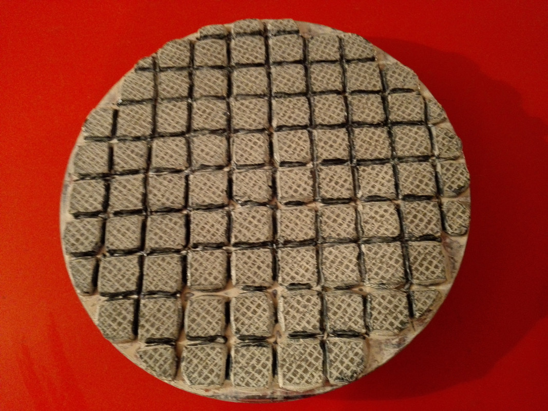
Maurizio, Would you be able to post a photo of the tool with a flat and close-up view, so that it is possible to evaluate the degree of wear of the patina ?
23 November 2015 at 11:57 #708023 November 2015 at 18:57 #7088Hi guys,
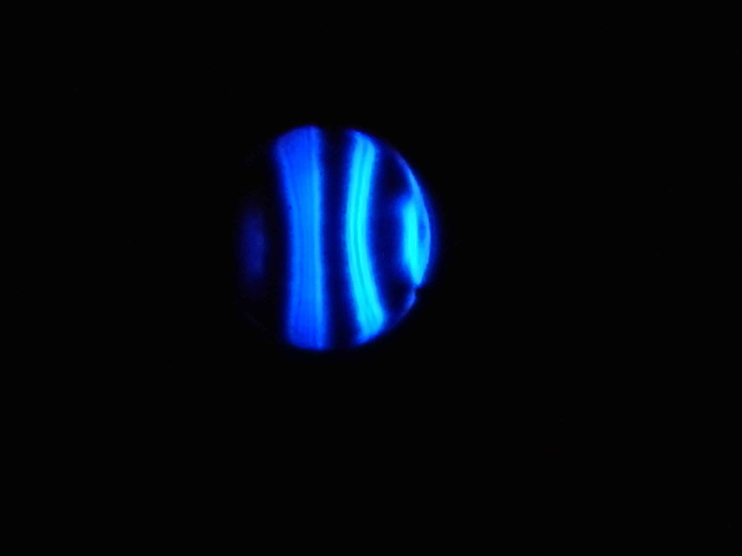
I think that in addition to the ball problem I also have a tester that isn't working perfectly
because’ sometimes after about thirty minutes of work I have images that tend to go to the left (at least there is some astigmatism) and then there is’ the left side not symmetrical with the right.
http://s10.postimg.cc/xvvc5szkp/IMG_20151123_174316.jpg
http://postimg.cc/image/ex2118sdl/23 November 2015 at 19:24 #7089Maurizio, the tester works well, the anomaly that you rightly found depends only on the light source which is not centered with respect to the mirror.
If you look at the right side of all the images you will see that there is a brighter area: that is the center of the LED which must be centered with respect to the mirror.
Considering that however the images are significantly improved compared to the first ones, I would say that all you need is this measure to have a perfectly functioning and calibrated tester.Regarding the patina, it is certainly well made, however I believe that the “net” that you use for adaptation and for the micro-groove is oversized, I would try to put the patina and mirror under pressure without interpositions, just wetting beforehand with a little’ of soapy water or even with the same cerium oxide.
I think it's worth trying, as Mirco had also suggested, to make sure that the bad fit is not caused by the pitch not being able to penetrate between the links and leaving areas without contact.
Have you tried reversing the mirror-tool positions? ?
23 November 2015 at 20:44 #7090Every 15 min I always invert mirror-tool 1/3 coc and then run the tester.
Then I'm making the passes as you advised me by giving light pressure with my thumbs with the mirror on top(but I didn't understand why I have to apply light pressure to the center) and even a little’ more slowly (I think they were faster before) while with the mirror underneath I always try not to apply any pressure 1/3 coc23 November 2015 at 21:39 #7091Maximum, I wouldn't even reverse the tool and mirror anymore, but I would continue to work with a mirror on top and that's it…I've always felt good like that…
23 November 2015 at 23:13 #7094Yes Mirco indeed… I had suggested reversing the positions because he was working with the mirror underneath, that type of defect is more easily generated with a mirror underneath and a tool with poor adhesion in the center.
Maurizio, I think pressure in the center can help, in this situation, to increase the processing in the central area which seems ineffective to me.
29 November 2015 at 20:16 #7109Hi guys,
in these photos I think I have made some steps forward even if I am not yet satisfied.
Then I think I'll have to put my hands back on the tester who doesn't convince me and then
I'm realizing how it varies depending on the adaptation and how cerium oxide works.
I couldn't take better photos than this
http://s22.postimg.cc/zeiw4tg0h/IMG_20151129_181641.jpg
http://s7.postimg.cc/r8f7etn7f/IMG_20151129_181916.jpg
http://s9.postimg.cc/f0jhqm1vj/IMG_20151129_182214.jpg
http://s9.postimg.cc/3vuj5c45b/IMG_20151129_182221.jpg30 November 2015 at 20:49 #7110hello Maurizio.
You are there and I am here and unfortunately I don't have the opportunity to see how to help you align the tester mirror and camera correctly, so that the light source illuminates the entire surface of the mirror well, and we can give an overall judgment of the Ronchi test, which is precisely a test that makes sense if it involves the entire surface of the mirror.
The question that arises is whether you see the disc of the mirror as in the photos, or fully enlightened.
Achieving that goal would be a major achievement, and it is the only door that opens the way to Foucault's tests, which would otherwise be impossible.
This is not to say that a good mirror cannot be made with Ronchi alone, if you know how to interpret it well. But alignment is precisely an indispensable condition also in Ronchi
1 December 2015 at 12:31 #7111hello Giulio,
the distance is too much to stop by and in any case your help is
that of Massimo and Mirco and me’ very useful, thank you.
Yes, I can see the mirror disc as in the photos.
My tester and’ to be reviewed because when it turns the threaded rod has small oscillations which are not good.
I wanted to ask you if you could clarify the mirror tester alignment for me in a few lines (If you have already written it, could you give me the link again?)maurizio
1 December 2015 at 12:49 #7112Yes Maurizio, the sensation is that of one “trend reversal”, the surface seems to normalize, obviously this can be confirmed or denied with good alignment of the tester. In any case, keep the operations in mind ( I variation at the selected ) what did you do to achieve this improvement, it would be better to write them in a “notebook of grattavetro” before each session ( Giulio docet
 ). In the comparison between the previous operations and these just performed there is the solution relating to the cause of the generation of the defect.1 December 2015 at 22:49 #7113
The use of a threaded rod to move the tester carriage longitudinally is a good thing if, however, you take care to eliminate the two disturbing movements that characterize each screw, that are:
– the so-called backlash, that is, the back-and-forth play necessary for contact between the screw and the nut that make up the transmission (but if that play wasn't there the screw would be blocked).
– the trend of the reticle trolley (or blade holder) to rotate for a fraction of an angle in the right-left direction or vice versa, always induced by the rotation of the screw.The first movement “forward backward”, aka the back-slash, you eliminate it completely with a simple elastic band that always keeps the trolley pulled against one of the two end supports of the track on which it slides.
The second angular movement “right left”, you eliminate it by ballasting the trolley with a weight of a few ounces.
For mirror alignment tester, you must place the tester in front of the mirror at a distance of double the focal length (which will initially be calculated based on the depth of the arrow, or measured approximately with the method proposed by Enrico DEabis in the article in this same blog titled “Determining the focal work in progress: a useful method in the phases of grinding”.
The height above the ground of your installation will be such that the center of your grating is at the same level as the center of the mirror.
The light source should be to the left of the reticle and as close to it as possible.When these conditions are verified, and the positioning distance of the tester is AROUND the focal distance, the mirror will appear fully illuminated when you place your eye just behind the reticle (or the Foucault test blade). Obviously you have to look for that position of full lighting to leave the tester there.
To bring the lighting to reflect at the desired point where you have installed the reticle, you should remove the slit from the front of the source so that the bright disk of the LED reflected by the mirror is much more easily traceable than the small slit.
Find the reflection of the LED dot by holding a white sheet of paper behind the tester.
Then that reflection must be brought to the desired point with movements of the tester around the optical axis, before putting the crack back in place.
At the end of the alignment all you have to do is make the lighting maximum and uniform across the entire surface of the mirror, standing with your eye behind the crosshairs as you finely adjust the orientation of the light source.At that point (thinking that in this activity it is the nanometers that make the difference), it is absolutely necessary that all alignments are not changed in the slightest for the entire duration of the test.
The position of the camera can be a complication of the setup because its lens must alternate with the eye in the same position behind the target, but it could instead be used in a fixed way to replace the eye, zooming in as necessary to fill the display, and then looking at the mirror image on his LCD viewer.
ENDBy applying the principles of these suggestions to your setup you should be able to see and photograph the entire mirror disk, so you can try to take photos “classical” placing the black lines of the grating in symmetry with respect to the center line of the mirror disk.

-
AuthorPosts






- You must be logged in to reply to this topic.