- This topic has 98 replies, 3 voices, and was last updated 7 years, 4 months ago by
Giulio TiberinI .
-
AuthorPosts
-
23 March 2016 at 3:53 #7636
After a long pause lasting several months, I finally got the processing of secondary RC.

The primary is completed some time, as you may remember those who have read the discussion dedicated, and also the Telescope project. So let's step on the design parameters for the secondary:SECONDARY (misure in mm)
Diameter 115 (actual: 112 , project: 107)
Radius of curvature at the center): -774
focal ratio F / D : -3.46
conic constant (K) : -5.126
Sagitta secondary convex (112): 2.02
Sagitta concave caliber (122 ): 2.4
as you can be seen in the overall scheme of the RC system developed with Atmos: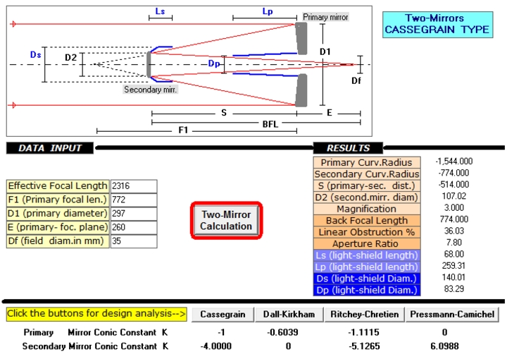
as described by Mirco in the discussion Secondary Cassegrain, and as explained in the theoretical aspects Julius article, to obtain the convex secondary will have to work two mirrors of which the concave act as “caliber” on which to build the convex.
the step of roughing / grinding, the same for both mirrors, It was therefore quite fast, about three days of work in which, in addition to complete the surface finish with the grain 800 It has been reached (with precision +- 0,1 mm ) the radius of curvature of 774 mm .
( In a future article we will describe the method used for the construction and testing of focal. )
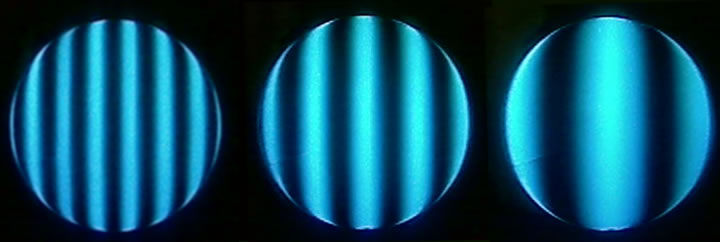
23 March 2016 at 3:59 #7639Started by today polishing of the concave mirror, This is the very first Ronchi after only 4 Polished sessions.
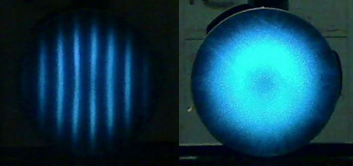
As you can see from the dark central area, The film was not well adapted to the center , se non sistemata, He would very soon generated a “collinetta” central.
Fixed adaptation to the changed patina “stella” of the tool 90% the mirror diameter, This is the next Ronchi after another hour and a half polished.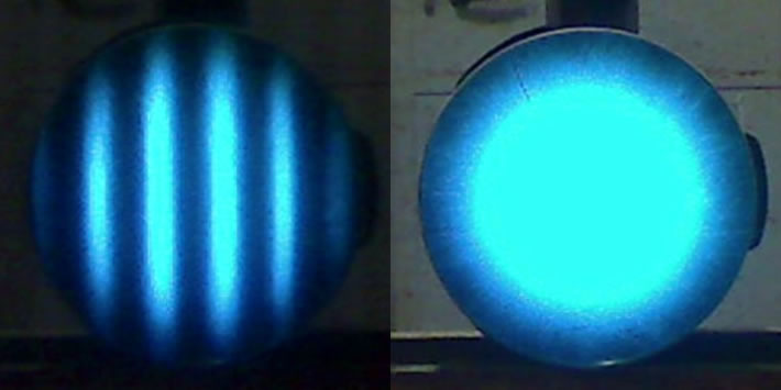
As expected, the periphery is “late” of center in progression to gloss, therefore, it reflects much less, partially obscuring the bands of Ronchi ( not to be confused with a faulty board ).
As I have always maintained
 , if everything is setup “in order” , there is no need to do anything, the ball is alone with the mere passed to 1/3 COC…
the difference in the processing of this secondary, and in general of the RC compared to the other variants Cassegrain, It lies in the fact that the conical constants are enough “extreme”, as well as very short negative focal.
therefore the “caliber” It must be brought exactly to hyperbole (positive) Secondary. In other words, you will have to first build the concave mirror bringing it to the same conic constant of the secondary, at that point it may be used as a reference for testing the curvature of the convex secondary.23 March 2016 at 11:34 #7642 I'm happy because I will read something interesting and very instructive!!  24 March 2016 at 0:34 #7645
Hi Massimo, after the hiatus'd say you're off to a…
the windows have already dug, changed the grits and now you're shining, but my camera was you who built scooter… A question: why you have opted for a modified tool star plus at 90% the diameter? how come you have not used the full standard diameter? There are special reasons?
Anyway great job as always, I can not wait to see the evolution of the work… 24 March 2016 at 1:26 #7646
You're right Mirco, a full tool diameter without modification, It would be the best choice
, the only reason was that I had already prepared the old tool from 115 mm con la “winter patina” ( a stella ) used for the primary, who had worked very well in his “first exit”, and he was ready to be adapted to the new curvature… I must say, however,, this time are not at all satisfied with how things are working the patina, despite the shape is acceptable, the glass surface is coming rather wrinkled, Perhaps the long period of inactivity, having spent a summer and a winter packed inside a box the hurt…

certainly for the convex it will be made a brand new coating for polishing and one for hyperbole.
Meanwhile I'm going forward with the glossy, After some restoration to the patina finishing touches, the roughness is a bit’ decreased, but still we did not…

 5 April 2016 at 4:41 #7689
Completed the polishing of the concave mirror alias “caliber” , now up to the convex
You see a little’ of retorted edge… there say that on a compact mirror 125 mm F3 is almost physiological to form, The small mirrors are terrible ! you have to work without the slightest pressure, just the weight of a finger just leaning, to alter the shape with a few strokes!
However in this case the edge retorted is irrelevant, the concave mirror is 10 mm largest convex in order not having to worry about the problems at the border, therefore it will not be arranged, I leave it as it is, because to take away the “small” edge it takes quite a bit’ of cerium oxide and elbow grease !
5 April 2016 at 11:26 #7692What about Massimo, very good sfera..complimenti…
I am happy to see and read that a slight edge retorted may be normal to form in a mirror with a short focal ratio since even in my mirror-caliber formed a slight edge…fiuhh…
Ah, forward to the polishing of the convex mirror, I suggest you check immediately with the interference fringes that the two curvatures are not too far apart and to intervene immediately with any corrective action, otherwise (as it has happened to me) the two curves deviate very far in a short time, and now, do I have to lose a great deal to groped to fix the problem…
Classics drawbacks that you learn to deal with the first realizations…
good job…ciao… 5 April 2016 at 14:26 #7693
Thanks Mirco
In fact, I decided to complete the first ball of his caliber on the basis of your experience with this process. I prefer to have a reference “definite” on which to perform the measurements and that way making changes. In this way, I am sure that every defect / variation of the form, at least for this first step, It is correct only in the convex mirror.Even because, as you know, the radius of curvature of the convex mirror is of fundamental importance for the whole optical scheme, ray, It can be uniquely defined only in the spherical shape and will have to be maintained (obviously only for the center ) until the complete realization of the hyperbola.
This means that the hyperbole of the convex side will have to be worked “from the center” namely, digging progressively from the center towards the periphery.
I'm curious because it is exactly the opposite of what I did to build the hyperbole of the primary
5 April 2016 at 18:31 #7694Things intriguing and interesting!
You make me want to scratch…even if only to reduce the focal length of the 300F6 to F5, 130F7 or the F5…Two things that sooner or later I have to do.6 April 2016 at 15:19 #7695From Giulio, forgive in motion all the equipment !
Then, as suggested by Mirco I tried to check immediately ( after two hours of polishing of the convex ) Newton's fringes between the two panes. however, having not yet built a tester worthy of the name, I had to, as my usual, improvise
I then used the red LED optical mouse ( and, I know it's not good it takes a diffuse light ) and my faithful webcam required to “closely” by two rounds of insulating tape ( I'll spare you the other details
)
I know that the result is a little’ disgust , But something you see, I promise that as soon as I realize the tester, the images will be best !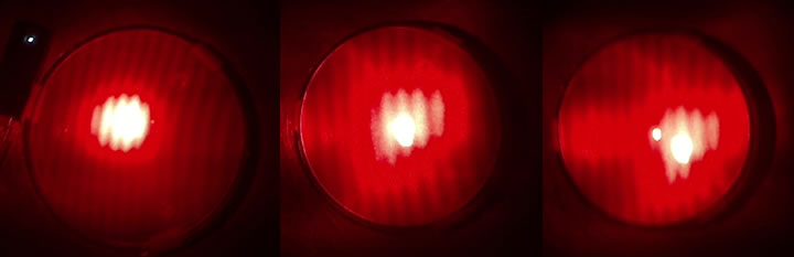 6 April 2016 at 16:16 #7697
Well crap just does not say, and then as you know Massimo, We homebuilders we arrange with all the imagination and we are not lacking…
Also I have not yet made an interferometer worthy of the name, and when I arrange how I like you too…
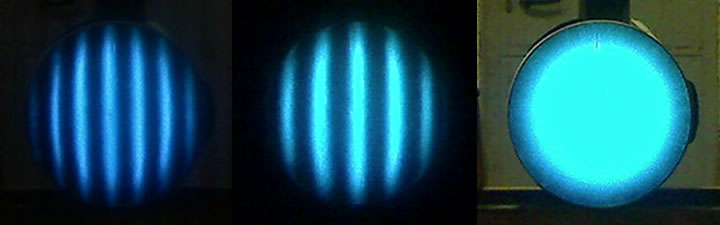
Regarding the fringes would say they are pretty straight sign that you're doing well (as usual) and that you're not moving far away from the scope… If you position the surfaces so as to obtain the circular fringes, how do you come out?
6 April 2016 at 18:07 #7712I do not know, I have not seen circular fringes
 how I should position the mirrors, in thicknesses without contact ?7 April 2016 at 8:21 #7713
I read that the concave surface should be resting against a flat surface; for example, the back of the tool plane, as seen in the linked text, in the table 1.1 page 10,
But of page 5 until 7 It explains how to understand the surfaces by way of moving poggiandoci fringes of a pencil in the middle or at the edge.
(a pencil and not a finger because the heating would result in something like the deformation of one or more fringes as shown in Figure 1.18 page 23, although the layout is different interferometer).Reading wondering if the samples to be superimposed should be flat on both faces, but I have found that only the two surfaces are in close “contact” that generate the diffraction lines, and the other two rear surfaces of the two overlapping windows would be irrelevant.
So you should be able to see the circles through the back of the flat face of your mirror leaning against the flat face of the tool.
I also read in paragraph 1.1 that when big the “gap” between the two surfaces in contact,(as in the case of a spherical surface in contact with a flat as shown in Figure 1.1, and I presume to be your case), It may be necessary to look at the fringes with a magnifying glass.
I understand, however, that this is necessary because of the approach of the progression of the fringes toward the deformed part of the ball, without the lens would see the gradually avvicinatissime perceiving them as a single thick line, while the lens or the usual microscope 15 EUR would show the separate.7 April 2016 at 10:06 #7714Hi Massimo, I'm writing about it now a little article that I hope to publish soon.
Anyway, the rectilinear shape of the fringes or slightly see the curve because there is a slight tilt between the two surfaces under analysis. If you see slightly curved it is because you are viewing a small portion of a circular fringe that would have its center far outside mirror (precisely because of the tilt). If you can remove the tilt, and ensure that the two surfaces are perfectly parallel then you will see the circular fringes if there is a slight difference between the two radii of curvature, otherwise you would see even a (because it already would be bigger mirror) if the two curves are perfectly identical.
To get the beautiful straight fringe (then with tilt in the tests) indicating that it was possible to generate the mirror surface “equal” to that of the gauge it is necessary that the two curvatures of the tool and for the caliber are precisely equal, or otherwise barely different. This means that to test a flat surface I'll need a reference flat surface, to test a ball I'll need to have a ball as a reference, a parable a parable as a reference and so on. If this does not happen, such as, for example, if we want to test a parabola with a reference surface which is a sphere, I will never see the straight lines, but I see it deformed a certain amount, quantity that must be measured and checked to see if the surface under test is good or not.
Clear that evaluate, also to the eye in a straight line, rather one that must have a precise shape or curvature is far easier, for this generally is used to give the mirror and the tool the same curvature and the same conic constant. 7 April 2016 at 14:05 #7716Thanks guys explanations, clear and detailed as always
From what I understand so far that they are portions of circular fringes or circular floods, it makes no difference, the important thing is the number of intersections ( rings or curved lines ) along a diameter, where the distance between two successive fringes represents half of the wavelength.So if I draw a straight line in a diameter and Interseco only a single fringe ( in phase or in opposition ) I am sure that the difference between the two surfaces is less than or equal to lambda / 2.
to see the fringes is however necessary that there is a layer of material different from glass that modifies the light path, in this case the air, without which there would be no interference, for that you need a tilt.
There is an interesting article, the site of NortheK's Massimo Boetto, that speaks of the interference fringes for flat elliptical mirrors, easily extensible concepts for other surfaces. Article moreover also “revolutionary” in some respects, I invite you to read especially the second part, where he speaks precisely interference and forms “alternative” for secondary plans.
-
AuthorPosts
- You must be logged in to reply to this topic.