A battery to power the fan aspirator of "turbulent boundary layer" present on the surface of hot primary mirror of a dobsonian telescopes, it is essential for any amateur astronomer wishing to maximize the performance of its instrument.
An amateur astronomer "visualist" , which therefore does not use hardware photo / digital, has not generally need electronics or "power tank" in the field, because the electric utilities in a dobson are ZERO, or at most low absorption.
The main of these utilities is constituted by the aspirator of the "perturbed boundary layer" almost omnipresent on the surface of the primary mirror when it is at a temperature higher than that of the observation environment, when you wish to high, or very high magnification observations.
To further clarify the acclimation arguments , turbulence and primary mirror cooling, see the following articlesthe :
Acclimatization of the optics of a telescope, influence on observation and possible fixes.
Fluid dynamic simulations of the turbulent motion of air, over a warm mirror.
Cooling telescope mirror
The possibility of having two suction speed is interesting enough to appropriately lead to better performance of the telescope, and as a simple and efficient thing, It is better than having available a wide range of adjustable speeds, since the very low of them, in practice they are almost useless as they lack the required incisiveness, and also by requiring a specific electronic hardware, that to the practical side is a "more" avoidable.
Going back for a moment to recall the characteristics of the aspiration fan indicated in the article previously cited, We can say that those of them having “dobsonian interest” are practically axial fans, of the type used for cooling the computers. One of the best brands remained the German EBM PAPST, including on-line, perhaps you can still download a very interesting catalog pdf. But today those objects come mostly from China.
It should however be stressed that, Although electric DC motors can rotate in both directions by reversing the polarity of power supply, is essential to respect the latter verifying that the direction of rotation or the generated flow, is concordant with an arrow printed usually in the plastic of the body of the fan.
This inversion in some recent models with internal diodes can no longer possible, because this kind of fan is always designed expressly for a use that never need inversion, and therefore constructively they are born with only one thrust bearing “rear”, placed on the side of the impeller which in the right direction of rotation that creates thrust.
This explains why a rotation reversal, while electrically permissible, It would not be supported by proper bearing and inflicting extra noise in the times, that means extra vibrations, deteriorating durability and efficiency, and especially. Vibrations that in our may be non well mechanically insulated fittings, they would run at the telescope eyepiece, the risk of turning in very small “ellipsis” rotating instead of the pin pointing stars in astronomical observation at high magnification.
The sizes of these fans are many, but the one I used, with airflow of 33 cubic meters per hour, It is the most common (and therefore economic priced at less than 10 euro), having the diameter of the impeller 80 mm, e 25 mm thick; Supply 12 It was CC ( but as usually occurs catalog work equally well with supply voltages halved, or increased by 25%).
Power 2.5 watt; Current consumption of just under 50 milliampere; Rotation speed 1500 rpm.
The low speed of rotation (1500 rounds) and low noise, as already mentioned, are always to be preferred to its the smaller vibrations caused to the telescope, and make it easier and more efficient with the simplest mounting foam rubber mounts.
POWER SUPPLY.
To remain faithful to the policy of using the “minimum hardware” to take on the field in the nighttime observations, my choice was to add the function of power supply by little modification in my portable rechargeable phare, or hand held emergency light.
Such a device was already part of my observational hardware, often used to illuminate the telescope mounting on very dark field observation sites.
However who does not have a lighthouse to modify as I describe, but still wanted to make the raw feeder, to be placed in its box without the light function, you will find at the end of this article the practical assembly diagram with the images and connection of the components of the strictly necessary hardware, as indicated in the wiring diagram that includes the lighthouse.
This Portable emergency light types are common in the world with many fellows , and it is (was) produced in series to operate with lamps 6 volts, and it contains within it its own charger 220 volt c.a., and one battery 6 was da 1,2 Amper hour, lead / gel, to ensure the duration of the illumination of 90 minutes like emergency light feature specification.
Then, thanks to the lead/gel technology, these sealed battery are objects capable of working at any trim and position.
My change consisted in the installation in the free space inside the handheld phare itself, of:
1) A second battery electrically and physically identical to the original (in my case AlcaPower of standard measure 97X24 h52mm (costs less of 10 euro),
The two batteries must be identical in order to be able to work in series and in parallel and to be able to receive an optimal charge
2) A little Triple lever diverter, having three-position switch with Central zero, sometimes referred to by its sequence of work “ON-OFF-ON”
3) Two fuse holder car type, with fuse choice from 2 barely. (Today is available from the car-electricians, tiny fuses holder for car fuses MINIVAL type from 11 mm width. The latter possibly in good version with integrated led which glows when blow the fuse).
4) A socket for the appliance plug power outlet to the fan, called power connector 12 volt direct current from 5Amper, with internal Ø 2.5mm and external 5.5mm
OPERATION IN THE THREE POSITIONS:
— 1) With the switch in the position 1, the two identical batteries are placed electrically in parallel, and both can be loaded simultaneously.
At home: To recharge the two batteries should be planting the cable plug to the net 220 220 volt network, with the switch in the position 1.
On the field: with the switch in the position 1 are present 6 volts at the output jack for the fan, making it run at speed (and vibrations) halved.
With the voltage of 6 volts the aspirator speed is halved compared to the nominal, and also halves its current absorption, that drops to about 100 milliampere; while the two batteries of the handheld phare put in parallel, add up their capacity in (1.2+1.2)= 2.4 ampere hours (that is 2400 milliamps hour); So the field autonomy aspiration at half speed will be (2400/200)= 12 hour. It is a fact that could possibly halve with cold winter and with seniority battery, but exuberant at least for the duration of my astronomical observations at the highest magnification.
— 2) With the switch in the position 2, the famous "central zero" (the lever is in a vertical position) the circuit added to the handheld phare is disconnected, but you don't have to connec the recharge to the mains (otherwise it would only charge the original battery creating bad inbalance between the two batteries, negating the possibility of a subsequent use in voltage 12 volts).
This "zero central " given by the position 2 diverter, it is very important for safety in the design, because it serves to avoid any temporary short circuit in the transition from series to parallel configuration, or viceversa. which could have intervened by fitting a bad two-position diverter instead of one good with three (as at first sight it would seem possible) which, however, would not have given a guarantee of closure of a contact of the series configuration, after you have definitely opened and deactivated the parallel configuration, or vice versa.
The installation of the fuse 2, and the reverse voltage blocking diode placed in series, it is precautionary and only serves to prevent a short circuit on the two batteries following a very remote and unlikely but possible breakage of any internal section of the triple diverter.
— 3) With the switch in the position 3, The batteries are connected in series, and on the output socket are present (6+6)= 12 volts they do run the fan at nominal speed. Speed most frequently used because it ensures a better cooling of the mirror assembly to the removal of the boundary layer.
NOTE: The diverter 3 position that provides output 12 volts, is to be ever used exclusively “on the field”, i.e. without contemporary electric connection to the mains at the charger.
This is because the output configuration 12 Volt is incompatible with the operation of the charger that provides just 6 volts. And if connected to the mains simultaneously with the insertion of the fan power plug, it would permanently damage the battery charger.
The two batteries of the handheld phare in this series configuration, They have the rated capacity of a single one of them, that is 1.2 ampere hour (1200 milliamaper hour).
Therefore the autonomy of the fan at nominal speed will be (1200/200)= 6 hour. Here is a theoretical data, as they probably could even halve with cold and seniority of the batteries.
The changes to the portable emergency light is indicated for the following circuit diagram, where the dotted rectangle represents the content "factory" circuit of the handheld phare.

On the outside of the headlight casing, the outer socket has been installed in 12 volts, and robust protection to guard the diverter lever (see photo (clik to enlarge)) , since the lighthouse is transported in the car trunk along with the telescope, in a condition to take bumps that could break it. 
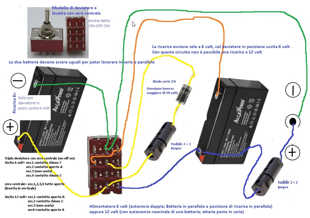
In case you want to build only the power supply, without inserting it to modify a hahdheld phare (which by now may have gone out of business over time) here is instead, the practical assembly scheme of the bare essential hardware, to be placed in its own box.
Obviously this assembly does not contain the charger a 6 volt that would have been present in the hand held phare. Therefore, to recharge the two batteries, a battery charger must be provided with an output 6 volts, to be connected to the positive and negative terminals indicated, in the left battery of the diagram.