WHAT 'GUI PLOP:
GUI PLOP is a powerful program for the project and the qualitative assessment of the primary mirror of the telescope support cell.
Why can be critical the mechanics of the cell supporting the mirror?
Who is the craftman is aware of the fact that the optical precision of an objective reflector telescope for quality “barely acceptable”, It consists in presenting a defect ON THE GLASS of its reflective surface (understood as measurement “peak-to-valley” of its worst bumps on the surface), such as not to exceed 68,75 nanometers high., or millionths of a millimeter, that degrade the’ WAVE REFLECTED of a value that is one quarter of the wavelength (lambda) of 550 nanometers owned by the yellow - green reflected light, to which the human eye is more sensitive: That is the famous “lambda/4.
And this is due to the fact that the wave, It is reflected in, It is damaged twice error on the glass: A first time in incidence and a second emerging from it.
And this double accident and emerging wave damage shows that to maintain wave a defect of reflection of Lambda / 4 , it is necessary that the glass owns a double accuracy, namely Lambda / 8, since:
Lambda/8 + Lambda/8 = Lambda/4.
obviously, since it is to reach at least the accuracy of 68.75 millionths of a millimeter tolerance, the mirror performance may also be significantly affected by deformations not own optics, but induced a mediocre mirror support, which in its cell can be brought to flex when varies its attitude pointing objects that are at the zenith or others who are on the horizon.
These possible deflections generate an additional error that is added to the right of its surface, potentially degrading instrument performance.
Who is the author of GUI PLOP?
The program is the result of the work of several people. As man's read in the window “About Plop”, those cited for the first importance is the author of the program, and David Lewis, engineer Toshimi Taki.
The latter is Japanese aeronautical engineer with the hobby of astronomy, and it modified for this purpose a specific tool of modern designers, which is the structural calculation method of “Finite element” , in order to apply it to design and verify the cells supporting the mirrors for telescopes, in such a way as to minimize the distortions introduced by their stresses which adversely affect the optical performance.
One of these cells support in fact, It is characterized by supporting the primary mirror in a series of points in the plane, whose arrangement is calculated in order to load on each of them, a portion of the weight of the mirror even varying its trim in the telescope pointing, to generate the minimum distortion of reflective surface(in function of the number of support points chosen), and with such distortion seeing the error of optical reflection expressed in RMS, or in ratio values peak / valley, that will overlap with other surface errors, contributing to the degradation of the performance of the instrument.
What is the “Structural calculation Finite Element”?:
It is the study of the behavior under load of a structural element complex urged from its supports (I our case, the mirror) , which is then divided into a NETWORK of thousands of components of a little size, whose behavior under load is describable with the approximation of algebraic equations, only reachable by with the power of current computers. Equations that describe this behaviour, coming to display in different colors the different degree of deformation of the different stressed zones of the surface under examination.
What is the utility GUI PLOP for the Stargazer?
The program allows in-depth technical evaluations that go far beyond the knowledge of the normal BASE stargazer self telescope making. However, with regard to "do it yourself" astronomical amateur, PLOP GUI is very useful for the design of the cell size of the primary of your own telescope.
But the use of the program is not so "friendly" and immediate. So not younger people like me, that use it very rarely, in time, forget "how to".
This is the reason that often prompts me to write the instruction "a reminder" for the benefit of myself. To fall back in time, in case My of future needs.
This script is then one....
PSEUDO TUTORIAL FOR USING THE PROGRAM GUI PLOP
…Tutorial here limited to a PRATICAL EXAMPLE of sizing the primary mirror cell Newton Ø300mm with 9 support points (but we will see that at the user is, however, reserved the right to choose A DIFFERENT number of support points desirables, in order to compare their values and choose the optimal one).
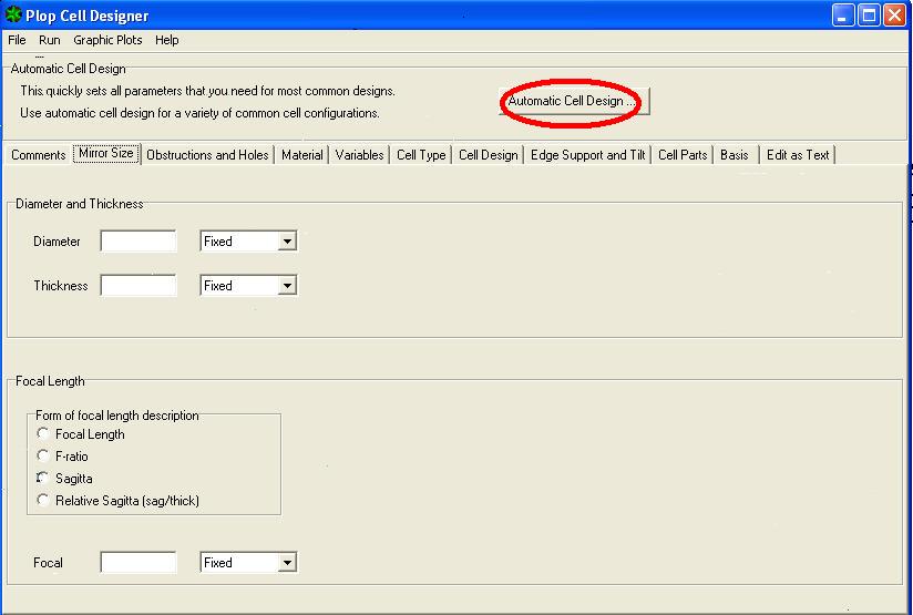
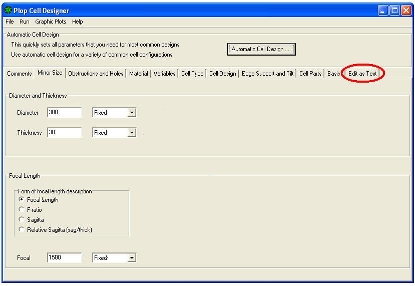
1) In PLOP window DESIGNER CELL click AUTOMATIC CELL DESIGN –
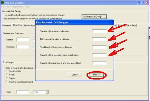
If after the window plops AUTOMATIC CELL DESIGNER, where to place the primary diameter 300 mm – 30mm thick – focal length 1500mm – diameter of the secondary mirror 67 mm – leave blank the central hole box –
2) click NEXT –
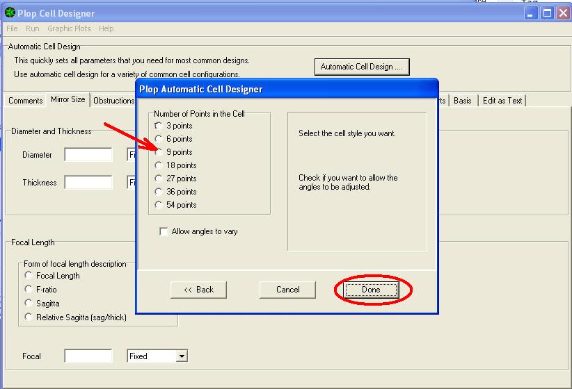
This opens the window for selecting the number of the cell support points
3) Choose the cell to 9 point and click DONE
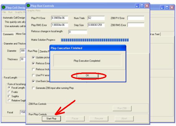
4) It opens the PLOP RUN CONTROLS window where click START PLOT –
the program processes the calculations and when he finished the communication window opens – PLOT EXECUTION FINISHED –
5) press OK. The following page becomes visible , from which, by clicking on the EDIT AS TEXT tab….
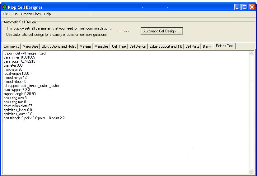
6) showing the following list of variables and relative calculation coefficients appears on the lower half page, than multiplied by the mirror diameter, provide the correct measurements of the inner and outer circumferences, on which they will rise (for our cell with 9 points) the 3 internal support points, ed the 6 external of the support triangles of the mirror in its cell.
7) Prepare to draw the cell with a CAD, or other manual drawing method:
8) First draw the primary mirror diameter circle (300mm);
9) It is now necessary to search, among the many rows in columns relating to the displayed variables, the one that will allow us to calculate the radius of the internal support circle, which is the VAR R_INNER 0.331085 – and then multiply the radius of the mirror by that coefficient 0.331085 to get the radius of the inner circle of the cell on which i will stand the 3 internal support points, of our cell at 9 points.
(150×0.331085=) 49.66mm = radius of inner supports
10) Draw this circle to be concentric to the mirror diameter.
11) Then between from the same rows and columns look for the variable of the external radius VAR R_OUTER 0.742219 – and multiply the radius of the mirror by that coefficient to obtain the radius of the circle on which there are other 6 external support points.
(150×0.742219=) 111.33mm = radius of the outer circle supports.
12) Draw this new inner support circle concentric at the preceeding .
13) Go to the MENU ’ of window PLOP CELL DESIGNER, and click GRAPHIC PLOTS, then click CELL PARTS:
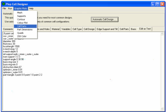
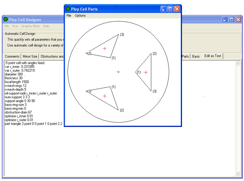
You will see the location in respect of the mirror were are the three isosceles triangles of support (due to a chosen cell is 9 points that provides in support of the nine vertex of the three triangles).
14) At this point, window closed PLOP CELL PART, we are still on the window below that shows the list of data already used. So to continue we must first close the EDIT AS TEXT file, by clicking on another file cabinet. For example on the nearby BASIS, in order to avoid the appearance of a blocking error “invalid floating point operation”l
Error that is due to an inconsistency between the comma sign, used by Windowws as a decimal separator in Italy, instead of the dot, Anglo-Saxon separator required in the calculations of the GUI PLOP program.
Calculations that we have to relaunch without displaying them anymore, to avoid the error resulting from the replacement of the decimal separator.
15) On the PLOP CELL DESIGNER window we click on the AUTOMATIC CELL DESIGN button, confirm with DONE the same data previously introduced in the RUN CONTROL card by launching START PLOP , and pressing OK when completed
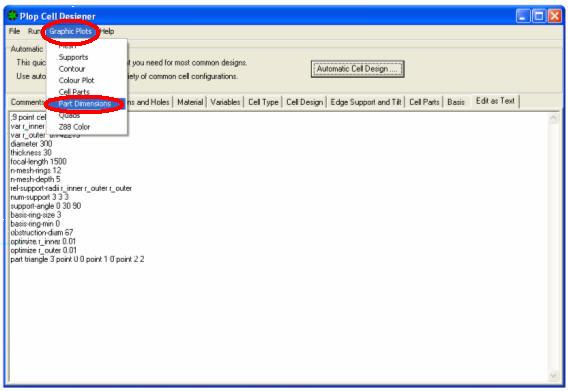
16) PLOP RUN CONTROL must then be closed and returned to the PLOP CELL DESIGNER window below, from whose drop-down menu GRAPHIC PLOTS choose PART DIMENSIONS.
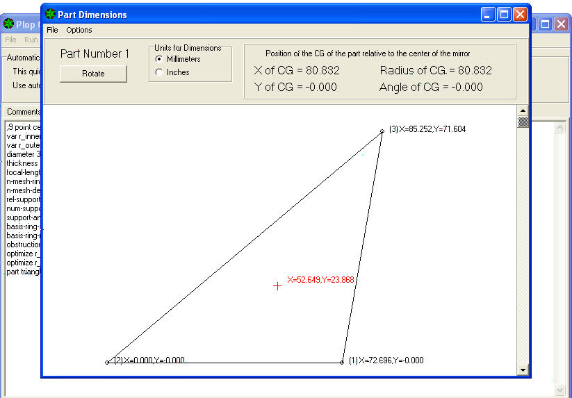
The PART NUMBER data sheet appears 1, which is one of three equal triangles, in Cartesian coordinates (in colour black) of the three vertex of support, and centre of gravity (in red) of each triangle, which will fall on a third circumference still to be drawn, lying between the two already drawn to the support points of the mirror.
Look at the BOX on top right, that indicates the position coordinates of the gravity center (CG = Center of Gravity of the piece displayed), givenin coordinates relative to the center of the mirror with:
X coordinate of the center of gravity = 80.832mm and Y coordinate = 0:
Which means that the vertical center of gravity (Y = 0) the center mirror, at a distance (radius) from 80.832mm center (coord. Y,):
Distance that identifies this third circle which lies, until 120 degrees away from each other, the three centroids of the three mirror support triangles.
17) Then draw the concentric circle of radius 80.332mm base of seat gravity points of the three triangles.
Looking at the triangle shape displayed, We note that both the vertex and the Centre of gravity are indicated in Cartesian coordinates , but this time refered to 2 (the vertex 2 lower left side) of the triangle, which has coordinates X = 0 and Y = 0, indicating the "zero point" of all measurements displayed.
The point 1 (the lower horizontal straight) Have then X-coordinate = 72,696 and Y = 0, which means that is long 72,696 mm i.e.like his abscissa, without variations of ordinate (because Y = zero).
18) We write that value not to forget it.
The window with the triangle displayed, presents the ROTATE function button, with which you can rotate the triangle counterclockwise, and lead from time to time each of its three vertices (The first of these was the number 2; the second will be the n. 3 and the third on n.. 1) in the point at – origin of coordinates X = 0; Y = 0, that is to the left of the image in video.
In this way, for each rotation that we will request, It will be gradually displayed the length of the side which is located horizontal bottom, indicated by its abscissa X.
19) we must keep notation even for those remaining two values, that with the first will identify the dimensions of each of the three triangles. (Two of these three values will be identical, because it is of isosceles triangles).
20) It only remains to draw the three triangles at 120 ° away from one another, by placing 6 points of 9 overall, relative to the extremes of their hypotenuses, on the circumference of radius OUTER (VAR = R_OUTER) 111.33mm;
And verify that the three points relating to their heights will lies on the circumference of inner radius (VAR R_INNER =) 49.66mm.
While their center of gravity is located on the intermediate circumference radius of 80.832mm
TAKE NOTE THAT: In this example of a simple cell with 9 points, the CELL PARTS is only one, that is the triangle for mirror support (in this case to be made in three identical copies).
While if you chose a cell having 18 points, the CELL PARTS would be two: That is, as a part 1 there will be the triangle for mirror support, (in this case to be realized in 6 identical specimens) and as part 2 the barbell bar that supports each of the three pairs of triangles (to be made in three copies).
And so also for other cells complicated by greater points of support, the display of data relating to the additional CELL PARTS is obtained by continuing beyond the display of element number one (which is usually one of the mirror support triangles), by making the mouse scroll down the cursor on the right of the window that displays the triangle itself. Any further constructive element will appear, in the usual way, showing all the information of its position, in the box at the top, and of its size in the center of the window , which may possibly be referred to the Cartesian coordinates of the element underlying horizontal the design, rotatable as described in the case of the triangle in this tutorial referring to a cell at 9 points, to identify the data from time to time relating to the side that is in a low horizontal position.
END OF DESIGN OF CELL.
If now we go back to point 13) PLOP CELL DESIGNER, and click on GRAPHIC PLOTS, We have the opportunity to choose to see other graphic representations of the mirror and its deformation when it were mounted in this designed cell .
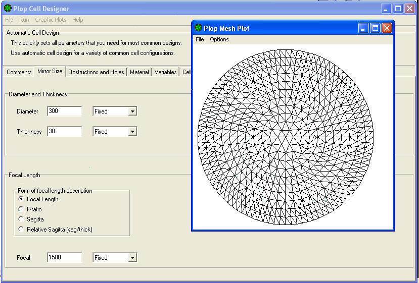
The first view, You can get by clicking on the dropdown menu GRAPHIC PLOTS at the voice MESH , to see how the mirror surface has been divided into the network of polygons of equal area, identified as the “finite elements” I am taken into account in the calculation.
The second menu item is pop SUPPORTS, that we had already seen above.
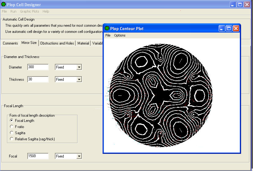
The third item of the menu is stress CONTOUR and will show the "level sollicitation lines" around the support points. A sort of contour lines, lines indicating the homogeneous level changes (albeit infinitesimal) reached by the deformed surface, same stress.
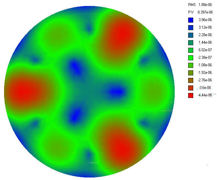
The fourth item in the drop-down menu is interesting COLOURPLOT that will display the map with the amount of deformation expressed even in relation RMS like “"Efficace value"” of the entire surface, AND even at local surface level in the various colors of a scale shown at the side, indicating values PEAK / VALLEYfrom the deformations generated.
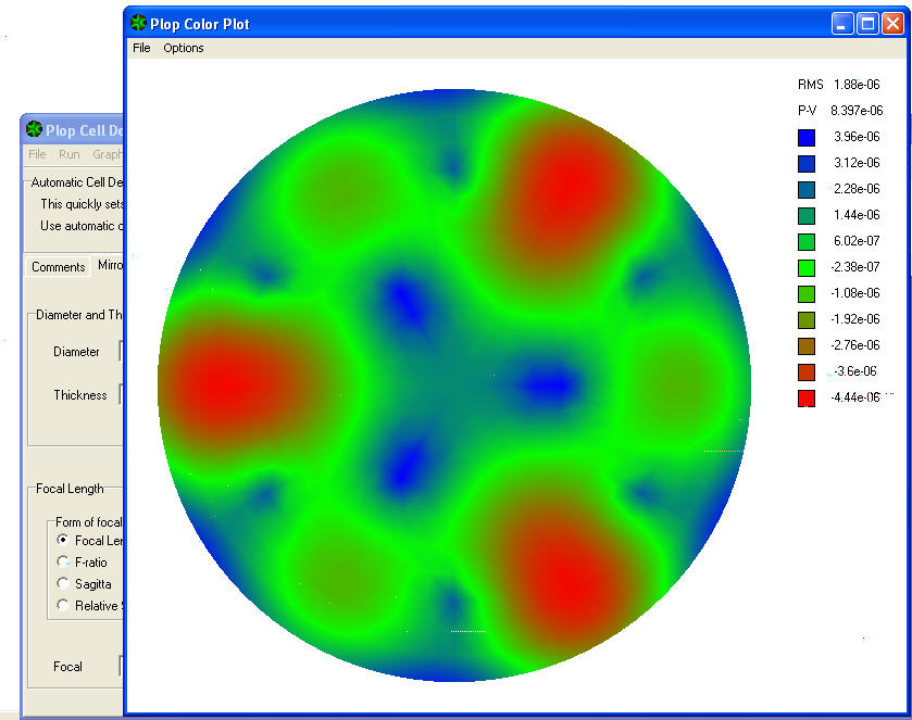
The RMS value 1.88 exponent-06 detectable in column at the upper right of the graph, It indicates the effective value (or mean square) error produced on the entire surface of the mirror by this type of cell, in relation to the wavelength (lambda) of 550 Nanometers of yellow-green light that the human eye is most sensitive;
While the underlying P-V 8,397 Exponent-06 indicates the error expressed as peak / valley, or local minimum and maximum deformation of the surface.
In practice, the areas in blue are those less deformed becuase well supported by the support points for the mirror; while the green areas are intermediate deformation, and the red ones are the most deformed.
How to get an idea of the goodness of the cell?
Even without resorting to mathematics for a techincally precise quntification, we read in the program guide“PloP user.pdf”, the suggestion that an RMS error of 4.2 Exponent-06 mm is corresponding to Lambda / 128, and it is to be considered a limit reasonably good for a cell.
Our cell complaint in the graph an RMS value of 1.88E-06, which is 2.23 times smaller and therefore better, than the limit defined as reasonably good for a cell.
Now that we made an idea of the magnitude of the quality of our cell, we only see what function have the remaining items on the pulldown menu.
We go ahead and end up jumping the fifth and the sixth entry CELL PARTS and PART DIMENSIONS, both already been seen above., and we meet the last entry “Z88” the drop-down menu, which it is not to our direct interest as it relates to the use of a software extension called for Z88 “insiders” of the calculation with the finite element.
fulvio_
fulvio_
Giulio TiberinI
fulvio_
Giulio TiberinI