- This topic has 47 replies, 3 voices, and was last updated 7 years ago by
Bartolomei Mirco.
-
AuthorPosts
-
4 April 2015 at 18:56 #5712
Hi everyone, at this time I picked up a mirror that I worked some time ago to try to improve it. The final form was not bad, but there was a slight edge retorted that led me then to ruin even more shape when I tried to delete it.
So the first thing I had to return to the ball, even if it means I wanted to try to get experience with machining, with discutibilissimi results.
https://www.grattavetro.it/wp-content/uploads/2015/02/sequenza-Ronchi-1200×485.bmp
All these errors were due once and for coating is not perfectly adapted, once and for too hard patina, once and for localized too much weight to the tool center, once for the wrong type of set up of the machine, etc ... but at least I have gained some experience ...
Because in the end I could not generate a good spherical surface are passed to the traditional processing hand tool with a full diameter and ran 1/3 COC.
Finally, after many hours of work I am managed to disappear almost all erroracci that had generated during the machining realizing a discrete sphere.
Although the second and third picture does not seem (I think the camera lens being dirty) the surface quality was very good, smooth and free of roughness and this could be seen very well during the Foucault test.
At this point, after further improved the sphere was ready to move to parabolizzazzione.
4 April 2015 at 18:56 #5713Before starting with parabolizzazzione though I have dedicated myself to redo the tester need to perform optical testing, because with time, what it had become more unstable and had arisen of the games between the components that were prejudging the reliability of the data collected.
And here's what I built.
First I made more stable by using the movements of the roller trolleys that are used for the drawers of furniture and I then replaced the threaded coffins to move back and forth with the carriage of the M6 step bars 1 mm (much more comfortable pace of M10 1,5 before).
I added several adjustment possibilities to make more comfortable the device setting during the test, such as having stretched the maximum extension of the longitudinal stroke of the carriage (110 mm. Useful for testing Hartmann) , the lateral movement of the carriage, the movement up-down left and right of the light source.
Modified the part relative to the light source, prefixing the light with a rotating wheel 4 circular windows on which they were mounted: a slit, a single blade, a hole stenoscopico. This to be able to switch from one type of ATRA lighting without fatigue and allowing me to switch from one type to another test with ease.
Submitted a height-adjustable support on which to mount the camera or webcam to create pictures of Ronchi or Hartmann's test.
4 April 2015 at 18:58 #5714PARABOLIZZAZZIONE
For this phase dispose of a tool to full diameter and one sub-diameter to 50% with modified edge star.
I left a couple of alternating dried using sub-diameter (classical technique for the W sub-diameter) in a few dried with the full diameter (Classic W always full diameter) coming in no time (less than expected) to the result that now I show and what time I have to leave to correct the mistakes that were formed. So the advice most welcome ...
I ran both the Foucault test that the Hartmann test and the results which now instead derive precisely from the data of the latter that I have recently begun to appreciate much more than the Foucault, during which always I find some difficulty to interpret the correct point of focus of the last outermost zone, this being approximately 20 mm radial width and that I value from about 4 meters, as well as the classic problem of finding the precise point of focus of the central zone.
Despite this, the two test results are concordant (as it should be after all), even if the entity (in nanometers) Errors are slightly different. So personally I am more inclined to take as good Hartmann the results being less prone to subjective interpretation tests.
and here is the result of the analysis:
and from this photo of foucault you can glimpse as the surface quality is good enough without obvious signs due to roughness (those dark spots you see are present dirt on the optics of the camera).
Of central hill for now I do not worry too much being, at least in principle, fairly easy to correct.
For now I want to concentrate on correcting both the raised edge, is raised above the intermediate zone.
Have you any advice? to correct the intermediate occupied zone would use a sub-diameter. It can go well subs 50% I already have or is it better to make a smaller one? if you than? same applies to the raised edge…Hello and thanks to all…
 4 April 2015 at 20:53 #5727
hello Mirco, beautiful and very interesting this report, complete with details and pictures as I like

Congratulations also to upgrade the tester, It deserves a nice article dedicated to design in
I would not give advice because I'm sure you'll do the right thing in the right way, rather, what you do will be for me to study and testing, on the other hand is not your first parable… I can say is that it seems to me that you're on a good path that promises good results, as it should be seen that the earlier you wanted to redo to improve further.
So I will follow with interest all development and… good luck 4 April 2015 at 21:18 #5728He did well to make the size tester not small. It also gains stability (My tester is not that great but weighted with 2 kg steel, the support, however, on a second base axis from stable and 50x50cm “pivoting” nl comfort with initial setup).
Me after mechanical experiments (and ballast), I zeroed the assembly of the first games by installing the binary as a metallic tube coating the usual threaded rod M6, sliding shoes with Teflon. While for the carriage maneuvering screw longitudinal I the screw / pin of the micrometer that directly pushes the cart always kept in contact by a sturdy and short elastic.
As for finishing touches, it is not easy to give advice being very personal. However I think I would look correct from the three humps individually with sub diameter (I saw my high degree of inexperience in that job) . Would I see better at first to “remove” at least forty, or also 50 or more… nanometers in all three elevations, surely with the use of the tool at full diameter without any pressure.(Obviously starting to do only two or three rounds of table, to see how “I go down” jointly, and it set on working times and accuracy general lowering).
This is because for the next phase, most likely this “dressing” I leave with the full diameter of a field “uniformly low”, and therefore ideal, or at least much easier to be corrected locally with sub-diameter, which it is certainly more effective and less dangerous, as limited as is his radius action and thickness to be removed.
In other words, the sub diameter used for small areas is much better sole alternative method the entire diameter with localized overpressures…..also because of the small diameter sub can get shortcuts for lambda double-digit impossible or very difficult to obtain with the full diameter.Congratulations anyway for the results and the “management”!
5 April 2015 at 0:39 #5738thank you both…

Massimo I saw you just posted a wonderful article on sub-diameters which I will certainly be useful.
According to you, however, that kind of past you would use in this specific case?
I would like to hear your advice, since the sub-diameters will definitely know more than me…
Giulio: They are a little torn between using the full diameter or sub, although I would finally learn once and for all to make good use of these sub-diameter… 5 April 2015 at 1:58 #5739
I responded “over there”, I had not realized that there was also a question “here”
I add only that it is crucial, even more of the dimensions to use, the choice of the points ( ie the annulus) where to lead the tool center: outside of such a crown / circumference of the curvature will be increased, decrease in. It seems trivial, but an incorrect choice significantly alter the expected results and we will return a flaw added to the existing defect.
10 April 2015 at 13:36 #5776Update:
In recent days I have dedicated myself to the repetition of the various tests to get a better idea of the actual shape of the surface, because the results I posted previously referred to 1 only tests and Hartmann 1 only Foucault, for longer carried a short distance from the end of processing.
Here I have said many times tests after he left to "rest" the mirror for the usual 24 hour.
the results are a bit different from previous ones (especially for error entities) more than for the shape itself of the same:It can be seen as both the center, both the edge, both the intermediate zone of elevated areas remain nonetheless, although in this case the center and the high board stem from the fact that they are still not near the parable, having as a curve which best interpolates the results of a conic constant K =-0,84.
The error profile of the surface to have imported into an Excel spreadsheet that simulates the Ronchi test, which as output me what should be the shape of the shadow bands that I see in my case.
P.S: sorry for the ugliness of the real pictures of Ronchi, but the light source and the slit that I used in this case are not really suited to get good photos, but it is the best setup for now I have found to perform Hartmann.
As you can see images of the simulator and the real ones are in agreement, sign that the shape of the surface interpretation is entirely correct in all.
In the light of these new findings before going to intervene with fine corrections, I think I will proceed for a few more annoyed with the full diameter or with sub 50 % with W ran to approach a little more to the conic constant K = 0.95.
10 April 2015 at 15:44 #5777I think you're very close, indeed close, I would think before you delve with the races in W. this defect can be easily eliminated with the sub 50%, and simultaneously bringing aumenteresti the curvature of the outer zones, if they are within tolerance, very next.
At that point would take a “ritoccatina” the central zone, surely the least problematic to deal.
All this of course if you've determined what was the cause of that rut in the middle area if it depends on patina, pressure or races…10 April 2015 at 16:56 #5779With that type of cut would be appropriate to proceed according to you then?
the groove according to me is still a residue of machining operations. In fact, just in that area passing most of the tool edge…
Although it was almost completely disappeared during the approach to the sphere, a residue remained and obviously I brought back so far…The next step will stand in creating new tools into pitch to adapt to rising temperatures. And for the first time I also am going to ever get them using pure beeswax and turpentine, substances that until now I have never used, then Massimo penderò cue from the data of your past posts..
for a working temperature between 13-16 ° C thought Use clean:
60 % rosin
40 % cera d'fire
10 ml linseed oil / 100g
6 ml trementina/100gSo a middle ground between the amounts described in the article “winter patina” (53-47 % pitch-wax) suitable for a working temperature between 12-14 ° C, and the ones I found on an old post in which you used the percentages equal to 66-33 for pitch and wax to a temperature of 16-18 °C…let's see what comes out..
10 April 2015 at 19:28 #5783That's what I would do:
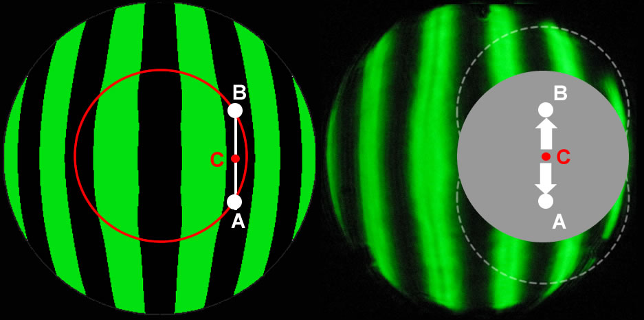
We have to identify the points of the compass ” mounted” of the curvature change, I listed them on Ronchi but likewise are obtained from the graph Horn.
on this circumference we choose the points A,B ends of the stroke of the center C, so that the sub covers the whole peripheral part.
With this past,with slight pressure to the center, always with slow and constant movement around the table, I'm ready to bet that in 10-12 rounds of table ( slow ) you've eliminated most of the defect.Is’ But it is important to be clear what we're doing:
Apparently we do one thing in contrast with the graph on the trumpet, ie go to deepen the periphery and consequently there “let's eat” a bit’ depth at the center ( that is already shallow his ).Why I would do this ? we need to do to display a graphic translation in this sense: the broken line connecting the values of the drawings within the tolerance trumpet, we can arbitrarily move it up or down, without changing the meaning of the graph. What we do is nothing more than a very small increase or decrease in value of the reference focal.
For example,, I take the entire curve of values and the stacker at the top up to the dropping point of the most extreme in the area within the tolerance zone, I'll have that all other areas must be deepened to enter in their turn in the horn area.
It amounts to saying that ” I hold good for the edge” and deepen all other areas, what is obvious:
– the extreme peripheral zone (7) almost nothing
– the next area towards the center (6) of ” a bit’ more”
– yet the next area (5) ” more and more”
– the zone (4) It is exactly where it passes the center of the sub-diameter, I will have the maximum depth.
This is exactly what will happen to outlying areas with the application of this past.
the remaining three inner areas will suffer a little’ predictable lengthening of the focal, but as I said before, They are arranged at the end, so it is the least problematic.After this intervention, the result should appear in Ronchi with a more uniform and steeper curve in the suburbs, except in the center where we will find a little’ predictable return towards the ball.
I think near the end parable, as in this case, where the edge is good, and the center has some shortcomings, it is best to keep as a reference because the edge is where we have less tolerance and a machining error is more difficult to recover, it is preferable to work the inner zones because the closer we get to the center we have more leeway.
I do not know if I was able to give a good idea and especially if you agree.for the mixture of the patina I also think that goes well as you thought.
p.s. I corrected the numbers, I realized now that the areas are actually 7…
11 April 2015 at 14:42 #5785Thanks Massimo, you explained very well…
I I think that I will proceed in this manner. In fact I think the best thing to do… 11 April 2015 at 14:47 #5787Wow! Rispostona instructive more than one item!
 12 April 2015 at 21:07 #5789
Feast your tools with a new cast of pitch-bees wax etc.…
I'm a little puzzled because in my experience the dough that I got, it seems a tad too soft (but I would not be wrong since it's the first time I use the pure beeswax and turpentine).
To make the idea, when I am going to affect the surface with the cutter to generate the channels, pitch not he rails, crumbles ,such as is seen in the videos of Gordon Waite, but on the contrary the blade sinks like themselves by engraving the surface of a candle…Is’ normal or is too soft?12 April 2015 at 21:48 #5790that's okay, what you did is a soft patina, if you remember the article I highlighted this aspect by saying that the channels are cold facts and a cutter, exactly for this reason,
If it is too soft, or better, if the ambient temperature starts to be too high for the patina, you miss it because the back and forth motion begins to be “rubbery”, but even then the patina can still work, it's just less efficient, but no less precise.In my case the winter patina begins to show these signals gumminess 17 degrees, beyond 18 in practice it does not work nearly as, but even in these conditions does not generate roughness, simply ” does not dig”…
-
AuthorPosts
- You must be logged in to reply to this topic.