- This topic has 142 replies, 6 voices, and was last updated 8 years, 7 months ago by
Giulio TiberinI .
-
AuthorPosts
-
14 June 2015 at 12:26 #6103
Mah, I have my doubts…

I tried to change the mask, to use different slots with different materials, ( also a pinhole ), putting perfectly at the center of the eyepiece the single slit but the result does not change:
There is always a longitudinal area of about two millimeters in which the image appears in the “best fire”, and moving within this range does not perceive any difference.
I wondered what the cause and I think he found it.
it made me think one thing you said Giulio:“For this reason I would have liked instead of Mirco hair, a "Hail Mary" ... or the text of the "International" written on microfilm, you can be able to read at least one word in order to be considered sufficiently focused.”In fact I tried to use a source-slit with as much detail as possible for thinking that, most are for the more details will be assured of the fire point.
look at this:
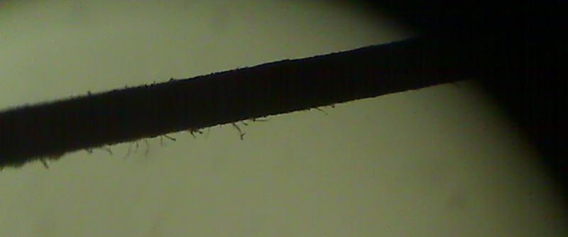
what you see is a wide strip 1 mm of a cardboard cut out with scissors positioned on the field diaphragm of the eyepiece. They are clearly visible “filaments” of the residues of the cut cardboard with scissors fibers. their thickness is definitely the order of hundredths of a mm.
I made a slit for the led, approaching two cardboard strips cut like the one in the picture, and I expected to be able to see the strings during the focus, but to no avail… even the shadow of filaments, indeed the edges of the slit seemed net such as those of the slit with the blades.
At this point I'm sure you already know what is the problem

we start from a simple calculation:
the resolving power of a mirror / hole 15 mm and 9 arcseconds , according to the known formula, R”=135/D
at a distance of 1500 mm , 9 arcseconds are the angle under which is seen an object of 0,07 mmThis does not mean that the same objects or smaller than this size will not be visible, but that only see their diffraction pattern, then if the items will be “quite” smaller ( as in the case of paper fuzz ) we will not see them at all.
The size of some of the gaps that I have used are comparable to the resolving power of the hole 15 mm, while for larger ones I've always tried to focus on the fine details which were not visible except in their diffraction pattern. ( and also in my “laboratory” in these days of open windows there is a bad seeing
 )14 June 2015 at 14:29 #6105
Cow! I had not thought about the resolving power……
 .And though it occurs to me that the image of the slit is said to be not directly accessible to the retina of our eye, with or without eye that looks reflected from the mirror while Foucault.
 If so, and I'm not taking a crab, It would seem that a solution could come in “overturn the omelette”, not trying to see that object into focus through the eyepiece, but to focus it on a small transparent plastic derision to install where there is now the field diaphragm of the eyepiece of the test, simulating what happens on a lens when adjusting the knife-slit parallelism.
At most, you should use an eyepiece or webcam to enlarge the tiny image.
————————————-
NEXT ADDITION: I realize reasoning in “freewheel” I actually took a crab. In fact with an eyepiece is the image of the slit must make visible (or a star through a telescope to infinity) in the focal point of the system, in which one must come to find the field diaphragm of the eyepiece.14 June 2015 at 14:44 #6107
Another reasoning leads me to think that it is indeed a problem positive identification of the first zone as a starting point, the only one that lies on the axis pttico, to calculate where they should be the distances X of the other areas of the mask corresponding to the hole centers.
14 June 2015 at 14:53 #6109So much so that Lecleire suggests use of precisely that kind of Hartmann mask with three holes to conclude that the area 1 It is achieved when the two images provided by the peripheral openings of the mask, with the longitudinal movement of the carriage of the tester, They are superimposed on the image coming from the central hole. In your case you have a central hole in the mirror, the two images may peripherals should overlap the two images provided by the two central windows of your first two areas that straddle the mirror perforated center.
14 June 2015 at 16:24 #6112the mask with three holes seemed I was more than anything else for the alignment of the carriage with the optical axis… I had missed this part
In any case, the problem is on all zones, peripheral or central. The “best fire” It is spread over a range of a few millimeters, for the level of precision required is an enormous…
mah…here you need a beer to refresh ideas
14 June 2015 at 22:36 #6114In fact, recapping the test operations (from what I understand) I would do so:
Once properly aligned to the optical axis of the caustic tester, with the use of a Hartmann type mask 4 windows (two devices windows of the mask that do couple with the other two windows coinciding with the center of curvature of the first useful zone, close to the central hole of the mirror)……Mask 4 windows that I would consider it valid for the mirrors that have a hole in the middle (and I say this as an extension of the principle described by Lecleire that relates to a mask with only three windows, one central and two peripheral, suitable for unbored mirrors at the center);
I would try the Punta caustic, but instead of using my method (described in the practice of my Foucault test) to find the same place, which is to the curvature of the two central areas center, and is the only PUBLIC STORAGE on the optical axis, I would use the method ( …my very similar to my knowledge….) suggested by Lecleire, works (while not understanding it well I deeply, and I tested to see in practice to convince) he says…
Placing the Couder mask and close all windows with the exception of the pair placed at h = 0.5 and use Foucault to move the longitudinal slide up to the eyepiece see the overlap of the two slit images in a single image (although it may not be well focused) at the point coincident with said point P, where the Foucault test would expect to find the spot on the optical axis, and detecting the extent of the draw…we imagine, for example, is 12mm.
Knowing the draft in the measured area with Foucault (Lecleire and says that if the mirror in question is already at least lambda / 4 value, you may very well take for good the theoretical value hm ^ 2 / R…for example imagine is 10mm)…
If the slit source are integral eyepiece, the exact center of curvature of the central area of the mirror, namely the caustic, it is found at 12-(10/2)= 7mm from the origin of the micrometric screw.Put the tester in that position, would install the caustic mask and with the application of formulas related to the equation of the reference parabola, I would find a number of values of the longitudinal axis X theoretical displacement , of as many positions are the zones measure ada.
For each of the theoretical values X must add the location in the draw point is located where the caustic THE TIP, to find the actual values of displacement in X that lead my longitudinal carriage in turn to the various theoretical X distances determined by reference parable.
longitudinal distances in which, acting only on the Y-carriage perpendicular to the optical axis, I should find the various caustic of the centers of curvature of the windows practiced in the mask, ranging gradually to outline the profile of the famous “"trumpet bell"”.
For the measurement of the first two or three zones starting from the center, would open only alternatively the post-it of one of the two windows at once (to avoid seeing overlapping slits and disturbed by diffraction fringes due to the narrow slit, which would render impossible an accurate evaluation).
The alternate opening of the two windows I would expect that should allow me to find the best focus of his image, at most with a longitudinal displacement of the carriage which, however, betray the possible inaccuracy of my parable in that area.EVERYTHING in the hope that the displacements necessary optical axis, not stravolgano the measure.
However, none of the users in the Caustic Cloudy Nights quotes the problem. And it could very well re-open the discussion with a question to the various gurus who have written to you, for lights.15 June 2015 at 10:59 #6119Thanks Giulio, excellent description of the procedure that will definitely be useful, unfortunately I am still at “dearest friend” , until I can not find a method / setup that gives the certainty of being the focal point of a zone it is useless groped to any extent…
16 June 2015 at 1:21 #6122An interesting article that describes a best giuducato method of caustic to identify the center of curvature of the areas , is that described Quii:
http://bobmay.astronomy.net/DAFTtest/dafttest.htm
Unfortunately (Leg) Is’ written in an ignorant terrific English, that leaves much to the imagination.
But the idea itself is not evil senbra, and consists in very obvious make the center of curvature of the zones using a pinhole in place of the slit, and to cause the production of two sets of diffraction peaks (such as those which causes the support to the secondary cross), series which overlap in the center of curvature to the fashion of the focus with the Hartmann mask.
The pinhole is hard to do (and to be illuminated). It trovavno many microscopic removing the Front Electrode (self-adhesive metallic tape) which leads the small holes from which come launched by the electrostatic charge of the droplets inchistro of cartridges for ink-jet printers, of the type that has the built-in cartridge uggello (all the old HP printers).
Instead my previous chat was only in order to see if you did not suggest anything that passage that I did not understand, reported by Lecleire to find the start of the caustic puno, with a subtraction of the X value found half of the theoretical value calculated X.
16 June 2015 at 12:28 #6124Interesting but missing of two elements which alter in reality the figure observed:
1- the diffraction rings with all due respect to Mr.. Airy
2- the contribution of the other burners beyond that reported to the central part of the area.However, it is precisely because of these two elements which is reached ( it was time ) to the solution, the key was provided ( as usual
) by your own reflection, as well as by the aid of careful consideration of Mirco:Jules said:: For the measurement of the first two or three zones starting from the center, would open only alternatively the post-it of one of the two windows at once (to avoid seeing overlapping slits and disturbed by diffraction fringes due to the narrow slit, which would render impossible an accurate evaluation).
I said and done I realized the narrow slits with two blades separated by a few microns, in some points the blades were in contact by breaking the continuity of the slit with small holes separated by dark spaces.
Taking up the point 1:
the diffraction lines were clearly visible at that point along with the semi-rings that are formed around the holes. The lines and rings were still visible in the usual range of a millimeter ( more or less ) longitudinal displacement to decrease of visibility until it disappears moving away or approaching the mirror.Taking up the point 2:
Each zone contains a parabolic sector and since the centers of curvature of a parabola vary continuously, also the image eyepiece observed in this test must necessarily show “fires” which follow one another with continuity:
I made a mask with only 4 circular holes 25 mm and these effects , as expected, They are even more evident.By combining these two criteria, you understand how it should be assessed fire
until -there is a unique focal point ( single center of curvature ), because in that case the sector would spherical.
b-there is a longitudinal range which includes all the centers of curvature in the area.
C-this range can be easily identified by the appearance of diffraction effects
O-the micrometric slit, within this interval, It will never be visible as a single thin line, but rather as a line (thin ) and surrounded by central “margins” still blurry ( other fires in the sector ) and the diffraction patterns. This situation is creating the “first fire” ie the shortest radius of curvature between those under consideration.All this is beautifully summed up in the image taken from the notes of Julius ( I believe it is the text of LeCleire )
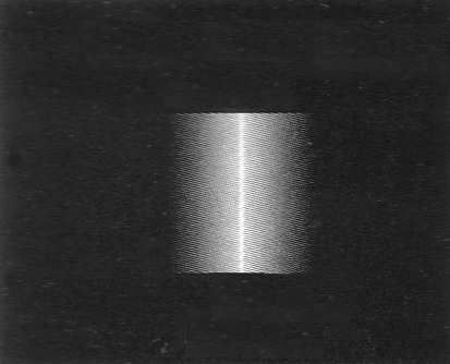
my mistake was of type “cultural”
 , For I have always tried to see the image of the beautiful cleavage focus, as I did watching any object at infinity by a telescope with a parabolic mirror. I would have to think like if I were to look for a fire telescope with strong spherical aberration.
This fallacy has led me so far judging blurred images similar to the one in the picture.This also explains why it can be used only a very narrow slit or a pinhole, because the image of an object ( hair or similar ) or a slit wider, make indistinguishable the various burners, giving the feeling of an image always defined in a certain longitudinal interval.
After checking everything tonight
, I think I'm finally ready to start the first measurement session. 16 June 2015 at 17:58 #6133the nice thing ( so to speak… ) It is that all this talk only serves to identify the start of the caustic
then you should not find” eye” the fires of the areas !
Indeed , for each subsequent area to be measured,the carriage is moved to the theoretical value calculated by the formula X. what is measured is only the distance Y between the two slits. If this measure is higher than the theoretical value of Y, the figure at that point is sovracorretta, if it is less sottocorretta
Considering that I have not even a central area to be measured ( I have a nice hole ! )…
however, it was important ( at least for me ) to understand what you are talking about !
16 June 2015 at 18:52 #6134I'm very glad you're able to overcome “cliffs straight” so fast.
This incident only underlines how certain technical and practical issues together, They must be experienced first hand to be able to completely describe later in disclosure, without giving anything for granted, but rather specifying “but it is not what it seems”.
It would be the task of the good popularizer or good teacher. Many however do not “down” in this more than natural level, because they do not have knowledge or because they have no passion.
17 June 2015 at 2:47 #6136First test:
As a first test, I used the mask with only four holes 25 mm per side.
The difficulty and the successful test is all in finding precisely the focus of the first zone, operation that is repeated at the beginning of each session, it takes a while’ practice and patience, but once you understand the “mechanism” We can get there with a good safety.
Everything else is pretty simple, It is not required capacity for interpretation, manually once you found the first fire, positioning the longitudinal carriage for each zone on preset values. Basically it stands where the theory tells us that should be the focus of the next zone. ( and in fact we find ourselves right there… )
At that point, it only takes a lot of concentration to accurately measure the distance between the slits, but with a good visual reference in the field eyepiece it is absolutely difficult to measure hundredths of a mm.
Repeating the measurements you realize how, unlike Foucault, the differences between the values obtained are contained very, so far the maximum deviation I obtained in a series of repeated measures was 2 cents ( The displacement of one hundredth of a mm seen eyepiece is greater than the width of the slit , so it is a clearly visible and controllable displacement ) . Taking the average then you end up with approximate readings micron.
This results reporting:
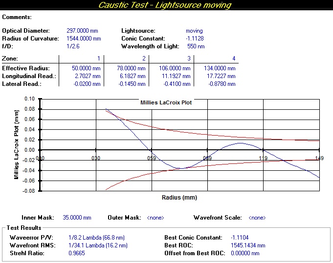
Clearly it is a very rough verification done on only 4 zones, however in line with the results of the Foucault especially on the value of the constant conical, although the hyperbole comes out a little’ “resized”

Tomorrow is replicated with mask 7 zones
 17 June 2015 at 7:56 #6137
Very beautifull!!
But what do you mean when you say “but with a good visual reference in the ocular field”?
In other words: What do you mean by good visual reference?Regarding the ridimensionqmenro of the curve, I seem to be a logical consequence of the fact that with these measures, and contrary to your previous way of proceeding, you left from the center.
….It would be ideal that you (it safe from messing up in the X calculations) I continue to go back from the periphery….Assuming that it is possible as it would seem at first sight.17 June 2015 at 11:04 #6139and, sometimes I express myself badly…
I meant the crosshair / copper wire or whatever is used as an aiming reticle for centering the slit in the eyepiece. It must be thin, perfectly focused and aligned with the slit, worth a bad / uncertain measure.
Ideally, your microscope eyepiece, with that you may take steps directly , in spite of any mechanical play micrometric.I thought about leaving from the edge , but the focus “manual” and the relative measurement is more difficult, the risk of errors is higher.
Resizing believe is physiological,as we said Foucault measure up to the overlap of the slits and does not take into account the “surplus” caustic. All in all I was expecting worse…
17 June 2015 at 11:33 #6140Yes I see that is not bad trumpet.
I thought it might be possible to run a normal “ROUND” Caustic from center to edge,but once he arrived at the top, adjust the best view of the caustic of that area, and the new distance calculation formulas with the new X reverse the backward path.
It is the eyepiece of the microscope I think is a removable block d(and reinserted) the appliance without problems, as a diameter of the cylinder (I go to memory) circa 15 mm and length about 30mm
-
AuthorPosts
- You must be logged in to reply to this topic.