- This topic has 17 replies, 5 voices, and was last updated 4 years, 7 months ago by
ConCalmaFaccio.
-
AuthorPosts
-
29 August 2019 at 19:00 #11517
Hello everyone. After my first purchase, un Robertson 150 mm, I was seized by the usual mania for greatness and now I want something more.
I live under the sky polluted the Po Valley, and if you do not want to be shot at home I have to please and I do not go around too much. If I really want to have fun so I just left the street to take advantage (very bad) a large diameter. I just pure space.
Thinking and thinking about what to do / buy I've come up with a crazy idea that only you, or veterans grattavetro, you have the skills to answer.
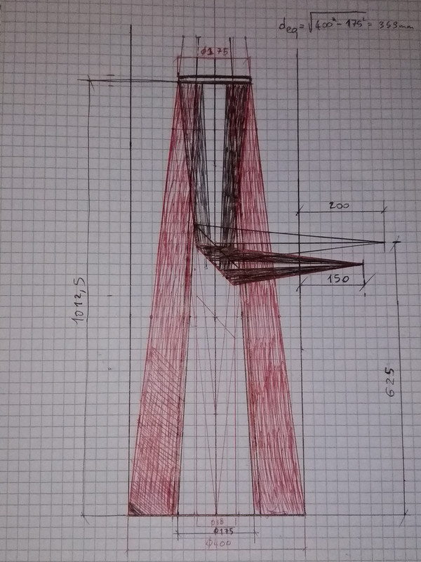
To make it simple it is an optical configuration that changes the type newton to have a shorter tube, and therefore less bulky (I do not intend to make a truss, but eventually will be a removable structure, with protections for the removable light). To do intend to include a flat mirror at about half the length is approximately half the diameter. Then the normal secondary newton him ride as opposed to about 1/4 Focal and vision becomes lateral as the type newton (non cassegrain). I saw that a diameter 400 mm with a plane mirror “intermediate” of 175 mm entails a darkening which makes it equivalent (not to mention the performance of the mirrors) to a diameter of 359 mm without any obscuration. It seems a good compromise.
Before you take the beast intend to build a smaller one for a try, maybe cannibalizing one in my possession. Will the motorized tracking, by ensuring that the stepper motor step are small making the engine run at a steady 60 rpm using Arduino board.
As the materials I use plywood and parts obtained from printing 3d wire. If you are decently it also molds the gears to make the reduction 1/86164 astrophotography.
During the designing process, It is basically my day job.
A mirror level… I DO NOT KNOW THE MIRROR PLAN AND CIRCULAR!
You understand well that without some good advice on compact newton project totally goes up in smoke, and I find myself doing something classic. I would not be satisfied.
All videos that I found, starting with that of Dobson, talk so much of the parabolic mirror, that as the first self-building experience I can also buy Chinese. And speaking of the secondary mirror all speak the secondary Cassegrain. BUT HOW TO MAKE A MIRROR PLANE CIRCULAR?
Given the cost of the secondary, visibly cut from glass rod with an inclination of 45 degrees, I highly doubt that the careful creation is less than that of the primary mirror. If enough take a normal oval mirror and cut everyone would do it.
HELP!
29 August 2019 at 22:39 #11518Hello and welcome ! Surely the problem of the plane of the mirror construction is quite complex, to the point that I do not see the convenience to perform a similar processing except for pure purpose “didactic”, ie to evolve and refine his knowledge in the construction of optical reflection.
Paradoxically, working planar mirror can be even more difficult than parabolic, area measurements should be made for interferometry, and it takes a proven technique of working.
I believe that as long as you remain on non-excessive measures, should buy it for two reasons:1-The economic cost is definitely lower than the constructive effort of “do-it-yourself”
2-Buy ( at least ) a plane mirror secured on the surface correction, means having a “caliber” to be able to independently carry out other flat mirrors that will be tested on the same gauge until it reaches the same optical correction.And if the decision is, however, to still groped, you can talk, we are here for !

I also rifletterei on configuration with three mirrors, which inevitably leads to not simple collimation problems. ( I know something…
)
Moreover, To lower the height of the eyepiece in a Newton, Also personally I would estimate the configuration “low riding”, with only two mirrors, as well described in a draft Giulio.30 August 2019 at 19:12 #11519Better know how certain things before you fail done shopping. I gained this day the fatal truth about flat mirrors. The reason why I wanted to make a compact Newton was not so much to lower the observation point (it's still been an interesting discovery, I not know them) how much to increase the overall structural stiffness and bulk.
Back in Training!
I have a few other options:
1) settle for a 300 mm f4 f5 about, which greatly reduces both the weight and the size (that the light ). Maybe just because of half the weight becomes beautiful hilarious.
2) sacrificing the small size of the mounted telescope and design a “very normal” 400 mm f4,5 (I can find “cheap”) removableI had already discarded for the manufacturing difficulties (First I should make me the bones) or the cost (shopping) the others 2 options:
3) learn how to build a Cassegrain – I have never seen large diameters: which suggests, especially for the corrector plate which closes the
4) learn how to build big mirrors very short focal length. It is obvious that this can be complex
Thanks for the explanation, now I come to throw down other ideas, comparing the 1) and 2)
31 August 2019 at 9:07 #11522Ciao. Welcome.
You've read, but frankly I have not figured out how to make that intenderesti compact Newton.You can make a sketch?
What I know, is that a plane mirror, even more if large diameter, It is very difficult to achieve, because it needs three tools of the same diameter, working with all three with alternations indicated by the spercie “truth table” type of computer, and using an interferometer as a guide.
If you will understand truly realize the large diameter plane, Your will certainly be a departure “uphill”.
On my return I could still make it in writing a tutorial article on that work.
I await your thoughts.
Ciao
Giulio 831 August 2019 at 15:14 #11524hello Giulio,
I saw some of your project forum, congratulations.I have some difficulty in attaching images. If you explain to me how to attach the photos I take a picture of the sketch on paper “concept” what did I do. The first expense that I will be that of a more serious pc where to CAD, although it will never be like what I have to work

I say immediately that in light of what I read in other posts that sketch should be improved (I have not taken account of the diameter of the eyepiece, I am only released from the tube diameter 200 mm as a parameter of “guide” because we own the focuser, leaving a second moment the details).
For a feasibility study that was fine.The fact that what we build will be for astrophotography implies a geometry that I have not yet defined (despite the dozens of sketches) because I have a lot of ambitious ideas about stiffness, “disassembly” and weight so I'll have to work a lot. One idea is even no real tube, with false cover for the light. But I still have to work several months before moving to CAD, especially if in the end I give up to the compactness of the mounted telescope because they give up to do so 3 mirrors.
31 August 2019 at 16:44 #11525Ciao.
If you have to insert mages you have to first upload them to a free host computer,(for example http://www.postimage.org) which in turn will give you some choices link with some link, among them you choose one for insertion of the image in a forum.
You paste into the address that your answer.
I believe that, Your dealing with a particular project, some image is essential to understand what it is.Technically, for example, one of only three ways to reduce the height of the Newton (at the cost of greater obstruction) It is to postpone downward the optical axis cone with a flat mirror inserted along its path, then to divert it with a tertiary elliptical outgoing floor next to the primary (kind “fire Nasmith”).
1 September 2019 at 11:17 #11526hello Giulio,
because of the explanation for the images.It's exactly as you described. The image shows a circular mirror plane that increases the obstruction of the primary, and finally the postponement on the tertiary elliptical.
As soon as you can around the picture
6 September 2019 at 20:27 #11527I hope functions,I'm trying to link the image using PostImage
8 September 2019 at 10:23 #11528And, as he said Giulio is a diagram with fire Nasmith, usually applied to Cassegrain configurations that allow the secondary obstructions smaller and more compact overall size.
In this case, the value of the obstruction is given by the position of the secondary plan that, however, it should take into account two other aspects to determine the actual size of the obstruction and the secondary same:
1-CPL, ie the full light field, namely the area on the focal plane around the axis completely optical “illuminated” by reflection. Being a photographic tool, CPL will presumably have the dimensions of the sensor that will be used, to avoid “vignettature” moving away from the optical axis.
For example, for a CPL 15 mm in the secondary drawing, in that position, You must have a diameter of 186 mm
2- HOOD: unfortunately a configuration which positions a tertiary that “look” directly toward the object framed, in the same way the primary, It brings light and unwanted reflections directly into the visual field, thus it must be provided for a hood system for all the mirrors that allow the reflections only for the primary optical beam. This will result in a further increase in actual obstruction.12 September 2019 at 17:11 #11529Hello and welcome on my part

Always nice to read that someone wants to try to embark on the road dell'autocostruzione!!!!
The project you propose is certainly not without difficulties, both for collimation problems he alluded Massimo, both, as you already said Massimo and Giulio, because of the difficulty in achieving a plane mirror which is very high. Difficulties which obviously increases exponentially with the increase of the diameter (as demonstrated by the prices of the secondary elliptical plans).
Realize then a mirror plane of 175 mm diametro, I see it difficult, as well as the necessary manual skills (but this certainly does not scare, otherwise no one never start anything), but especially for the equipment needed to test, first of all the need for a mirror of diameter at least equal floor, already optically floor, to use as a reference.Beyond all the difficulties listed above, that in some way you can deal with and more or less overcome, ti discouraged to embark on the construction of the optical configuration as well as you thought, not so much for the realization difficulties, but because it is a configuration with optical performance NON acceptable (especially if you want to do photography).
The motivation lies mainly on the value central obstruction due to secondary mirror plane. Value which in your case is 50%.
The central obstruction produces a decrease in the contrast in general, Not that a decrease of the Strehl value. The introduction of a central obstruction also, It induces a negative effect similar to that produced by spherical.I carry this link where you explained everything very well (Also the two previous pages in this):
https://www.telescope-optics.net/telescope_central_obstruction.htm
Beyond the whole explanation, which it is quite complex, to synthesize the issue, you just look at the first graph in the upper left of the linked page. Again the question is more complex, But beforehand you can see how already perfect perspective, the maximum acceptable obstruction, not to fall below the 0.8 The Strehl, he was born in 32-35 % circa. If then it is obvious how the optics at your disposal has a Strehl below 1, the maximum central obstruction decreases to values that are much lower, of the 50% the optical configuration you proposed.
This does not imply that you can not categorically make the optical configuration that you have proposed, but only that doing so, performance resulting nullify all the efforts made for the realization.For these reasons, I would recommend you evaluate other optical configurations.
Hello and see you soon,
Mirco 18 September 2019 at 23:37 #11533Thank you so much guys! You're opening up a world. I will start to build me a classic Newton. Now I have enough elements to understand why no one had done it before. Massimo's speech is clear to me. Really I had not thought. At this point, given that a diameter telescope at least 300 I want to build, I think that I need to focus on two other points:
1) beautiful the link you shot me, Mirco, but you'd know I recommend one or more reference books argue that everything in a certain order by “base”? As a cultural basis I did mechanical engineering and I have no problems with English and French. In other languages they are not at a sufficient level for technical studies.
2) I am reading other posts I started to look at all the most popular printers in the 3D market. I am strongly fought: for little money (circa 450 euro) I found a pretty good printer (+-0.08 mm) but it prints only PLA or there are other printers that are also ABS but have lower tolerances (+-0.2 mm or worse). The PLA on paper is not bad at all, in that it has a young modulus 1,5 times higher than the ABS. Also loads for this application “almost static”, then it worries me just the tendency to brittle fracture. I'm more concerned that I will “Dough-Boy” the mechanisms. Other materials are very interesting (example PLA or carbon loaded nylon) , but it passes at least 1500 € Printer. For the PLA simple, it seems that just be careful not to leave it in the car. But you, in that printed material?19 September 2019 at 11:23 #11534hello ConCalmaFaccio.
doing local mind on the type of telescope that Newton would build to use it even in astrofotohgrafia. you step a few links that you can afford to shed light on possible design features at the level of DIY.On the issue of full frames of construction, Newton and Cassegrain telescopes, starting from the creation of the mirrors, the FREE text, certainly some’ dated but for its fundamental nature and conceptually timeless clarity… is “the Bible” in the field, and is the French book by Jean Texereau “The construction of the telescope amateurs 2nd edition that has now pdf, downloadable chapters or whole
http://www.astrosurf.com/texereau/Since the Newton to make photography has an important dimension, and the best frame constructible amateur (course in my personal opinion) I venture which is that “Horseshoe” like this:
https://www.webastro.net/applications/core/interface/imageproxy/imageproxy.php?img=http://www.astrosurf.com/zeubeu/T500/IMG_20150705_102529_bis.jpg&key=81b9063bcf422a0586282feb8676fc7a21eda6615d468edaa6462962f40aaff6Is’ designed to accommodate a 500mm diameter Newton, but for the moment it is not shown the anchoring of the tube 500, but it is shown with a board supporting a dobson diameter 300mm
…We therefore suggest you take a look at the coming discussion of project that image, which is at the following link:
https://www.webastro.net/forums/topic/132038-construction-dun-t500-et-de-sa-monture/?page=7As for your point 1, REFERENCE TEXTS: From the point of view of the optical link that gave you Mirco is part of a very extensive and thorough directory of optical astronomical topics.
3D PRINTING:
Given that I know very little about the 3D Printing, but I have some knowledge on plastics; They are led to consider the PLA not reliable nor lasting mechanically. It would be much better Nylon 66 or polyethylene. I doubt, however, that the type of printer suitable for these wires is available at costs practicable for the hobby.
Even our writing has experimentally tested the feasibility of printing a Foucault tester, which, however, was not satisfied. then I see the press 3d relegated to a rather marginal use.As for the CAD, if you do not have it yet, I suggest you take a look at what nEach much use, that neither DOUBLE CAD – TURBOCAD LTE5 . It is a free open source and quite similar to the profile Autocad, opening and saving well in DWG. The use of infrequently, It is non-invasive and runs fine on Lap top HP is not recent, that purchase used and reconditioned with guarantee at “Simpaticotech”, preferring “old” senior HP machines and much-performing, purchasable among the 200 and 300 euro, ex leasing industriali, placed in position and secured.
19 September 2019 at 17:34 #11536hello Fabio,
Absolutely recommended the text you indicated you Giulio
Aaah well, then we are colleagues, I also have mechanical engineer
The 3D printer I have it at home anchio, I paid 200 € (to assemble) and use it regularly and there around the mold. I think it's one of the most well-chosen purchases I've ever made!!!
The PLA is easy to press and has a good mechanical resistance, However, as soon as salts with the temperature it tends to sag. To give you an example I had printed a cell door to put on the handlebars, GPS tracking to keep me in the hand, for the laps that I did. Well, remaining exposed to the sun, It is afflociato under its own weight (not to leak for charity, but she has lost its original form). So the PLA is easy to print, I often use, even for parts of my telescope, but it has its limitations.
The’ ABS moooooolto better resists to high temperatures, It has a good mechanical and abrasion reistenza, but it is much more difficult to be printed, They need higher temperatures, both the nozzle of both the plate and tends to detach more easily from the printing plate, making ears or worse, to the workpiece under construction.
However almost all printers are capable of printing these materials, others could not tell you.
Hello and see you soon
Mirco22 September 2019 at 12:32 #11537Thanks Julius and Mirco, it is important to have feedback especially in the preliminary study phase.
Anyway, Giulio, I do not know whether to be happy to have thought something good and tested or be depressed “not original”. In the picture I've shot I saw in REALIZED essentially the sketches of my last 2 months. And me, I had only seen the classic fork mount, I thought I had invented “a new cool”. Oh well.
In reality, what I am designing has important differences from what I've seen.
First of all, mechanics. I will not use pulleys and friction wheels. In the field of machine tool was used, until recently, a mechanism to 4 gears for each speed reduction in which a spring created the “zero backlash” between the teeth. The modern machine tools using 2 engines and electronics. I intend to make the gearbox backlash making a reducer 1/86164 zero backlash and associating an engine that goes to 60 rpm. The last wheel has a stretch of gear (imagine a curved rack) allowing a few hours tracking. The engine I turn it on just before he “found the target” with 2 idle movements from block. In two idle movements there will be other 2 backlash mechanisms, micrometrici, in the future motorized micro adjustments if I have time to play with electronics, I try to always have that pointed to perfection.
But I do not have the space to keep this thing whipped. So I'll have to do the whole thing as a removable transformer to be put away. It will have a type configuration trolley for transporting. Knobs will block the macro components in a configuration, and the other.
A normally use expensive cad 3d work that I can never afford to be private, especially avoiding too risky piracy. But even so my PC could never run them as you have
So for the 3D CAD I will assess what I find. I know a non-parametric CAD 3D for free, but not in mechanical parametric stands for insults to our lord. I do not remember what “good” He was managing assemblies. Another 3D CAD parametric, free, ma “creepy”. Meanwhile, I'll try to see what I recommended Giulio.25 September 2019 at 0:10 #11538Just being able to "not original".
For professional experience of mechanical design requiring intense “brain storming” between the technical experts, I would rincuorarti not to feel depressed for not being original state, why in the world, even without our knowledge, everything has already been invented by others, at least in the functional principle; at most and only modern technology, Unknown once, can change something for the better.
Often a seemingly unique solution, It is no longer such deepening the study or discovering that already exists in some kind of technical use. If, however, also an undesired micron movement becomes adjustable and deleterio..allora problems and costs rise dramatically.All that said, , if there are, should look for workable compromises, for example, if it does not consist in a limitation not being able to reverse the motion, it is easier to obtain the absence of back-lash being able to pre load in reverse motion an axis (even just with the example of the telescope tube weight) saving in constructional complication.
A pleasantly beautiful activities is definitely the design in itself, especially if you have no time deadlines.
-
AuthorPosts
- You must be logged in to reply to this topic.