- This topic has 71 replies, 5 voices, and was last updated 2 years, 6 months ago by
Bartolomei Mirco.
-
AuthorPosts
-
24 April 2020 at 13:44 #11739
there is definitely a deformation, you have to see how much… but if you don't put it upright how can you test it ?
I think that if the deformation is greater than the tolerance limits the results of the various tests would not be repeatable between two different test sessions with the mirror rotated. So it would mean that the meniscus cannot be worked and tested because the deformations would be higher than the values we want to measure… a terrible scenario,
 I hope not
  24 April 2020 at 14:51 #11741
I will try as soon as possible to do some simulations on the deformations, let's see how much they come.
A solution to test the mirror without having to hold it vertically, that I also tried some time ago, was to put myself to perform the various tests on the flight of stairs (I was on the landing eh), in this way the mirror remained in his cell and a little inclined, part of its weight like that, it was discharged into the supports below and not on the side edge.
Or you need to make yourself a dobson with twice as long pylons, so perform the tests with the mirror perfectly horizontal, from the eyepiece barrel 24 April 2020 at 15:12 #11742
In theory yes, in practice the caustic test in particular, where values are measured to the hundredth of mm, I see it hardly feasible at more than two meters high, it would take a vibration-free scaffold where to place the tester and another for the operator.
However if you do simulations, consider that the supports of the mirror are a 45 degrees and not a 60, I had long ago read a study in which it was said that it is the value of minimum deformations for the vertical mirror.29 April 2020 at 1:09 #11750Hello guys. I point out the interesting assessment / verification (in French but translatable fairly decently with the right mouse button, su Google Chrome) on the rigidity of the meniscus mirrors, in comparison with those concave planes of equal thickness at the edge, performed by Pierre Strock, passionate nuclear engineer self-builder of French telescopes.
29 April 2020 at 22:46 #11758Interestingly Soo, thanks Giulio
I have to read it calmly and compare their results with the simulations I'm doing too
Ciao
Mirco2 May 2020 at 1:39 #11762Jean Marc Le Cleire's French book explains how to correct astigmatism with local subdiameter processing.
In practice there is astigmatism when the mirror has two meridians with different radius of curvature: The focal closest to the mirror is called the tangential, and it is the one with the shortest radius on which you can scratch; while the most distant is the Sagittale.
It is therefore a question of identifying that meridian (that at the star test would present the stretched image in intrafocal), and mark it with a marker.
Identification of the tangential meridian, on the book it is described with the foucault tester “DEL FILO – (wire test sul Malacara) modified with the slit made rotatable; to which it is possible to remove the blade and replace it with a vertical wire of about 0.1mm diameter which can also be rotated by hand.
The tester is then brought with the blade to the center of curvature of the area at 70% diameter, notoriously the least distant from the sphere in a mirror in progress; remove the blades and put the vertical wire in its place.
In the area 70% a large letter will appear in the mirror “BE” upper case whose circle and straight line are the image of the wire centered on the area 70%.Then turning the slit and thread, the letter Fi also rotates, and one should be aware of the possible presence of astigmatism, when the letter FI begins to decompose into an S type with a spiral galaxy type.
Then rotating the slit and thread in the direction of curvature of the spiral, it will be reached again when the letter FI is recomposed, when the black diagonal will arrive on the longest focal meridian. which consequently is perpendicular to the workable meridian to be marked with a marker.then a +45 and -45 ° astride that workable tangential meridian there will be two imaginary diameters that will divide the mirror into 4 quadrants, the two straddling the offending meridian are those that can be worked with small diameter tools, to lengthen their focal length and unify it with others 2 major focal sectors, doing zigzag runs of small amplitude describing in each of the 2 dials a capital letter T.
The difficulty is that in any case it is necessary to arrange a full diameter tool with which from time to time it is essential to regularize the work.I don't remember what book I saw pictures of Mr. Maxutov brandishing lightened tools in multilayer disc (specific weight 0,4) used as support and reinforcement of the thinner large diameter plaster (specific weight 2,6).
I'm looking for if I can find Maxutov, and I will translate and send you the pages of the book
Giulio night2 May 2020 at 15:26 #11767Hi Guys!
The virus hasn't caught me yet, as I hope of you.
But for over seventy I stay at home and mess around “multitasking” , how to prepare to mount (never done in my life) a new rear bicycle wheel for my Graziella folding type with 20 wheels″, installing a three-speed Shimano hub gear, and work “Corali” etc.Massimo you say [Quote]
Therefore it will be necessary to understand how to intervene on astigmatism with a sub-diameter. I must say, however, that intrigues me, I have never worked on this type of defect, and I still have no idea of the solutions, if not that ( all to be verified ) to start working locally according to the tool diameter on the mirror center, until it reaches a central spherical area and then gradually extends outwards. Mah… [Quote/]I know well (in the sense of only having read it correctly) the local correction system of astigmatism with sub-diameter tools (although in any case alternating with passes of uniform full diameter) described by Jean Marc Lecleire in the French book: ACHIEVE YOUR TELESCOPE.
Of course it is a dangerous system because it is likely to create zonal errors, compared to a classic work with a full diameter tool to return to the sphere. But if experienced by you, it will certainly bear good fruit. Why then, how do you say “when i go…this vò”!As for the full diameter tool, I remember seeing pictures of Mr. MAXUTOV himself, brandishing a large tool, but light because built with plaster “thin”, anchored to a large diameter plywood board, drowning I think the usual mesh and screws.
I try to find out if I find anything on 3 historical ATM volumes of Ingall.See you soon
Giulio2 May 2020 at 16:15 #11773Thanks Giulio, the link works
and I knew you would bring out the usual “rabbit” from the cylinder
Now there is a good way to study it, even if from what you say, the use of a full diameter is foreseen, which I would not do for reasons of size and handling… we see, any ideas based on this study will surely come out !1 June 2020 at 17:22 #11849Hi Massimo, I follow with 'interested’ pay attention to your project.
In the first post you leave already’ from a meniscus glass – I can ask you if you made a topic dedicated to that phase?
As for the meniscus, you are aware of Tom Otvos' work in Canada?
I hope to see your next posts soon.
Regards,
Michele2 June 2020 at 11:37 #11851Hi Michele, I didn't write anything about the realization of the meniscus because I didn't do it. I commissioned the work for two thick glasses 20 mm with spherical meniscus ( one from 60 and the other from 80 cm in diameter ) to a company in Pisa, which creates curved glass with the mold softening technique and subsequent annealing, mainly for the nautical sector.
So I could not follow the various stages, but I could see that the finished glass is far from being spherical. ( not that I expected who knows what, even if a little’ I had hoped for it )
)
I mean that how “furnishing item” it looked spherical, but for the needs of us glass scratcher was so far out of the necessary tolerances to the point of requiring a complete reconstruction of the shape starting from the abrasive 80 until polishing.
The main problem was in astigmatism, the meniscus “freshly baked” it presented several radii of curvature in several sections with a difference in depth in some points of almost 0.5 mm, “Invisible” with the naked eye, but devastating for optical use.
With the sanding I managed to eliminate almost all astigmatism, currently after a partial polishing, only two perpendicular sections remain that have a different radius of curvature , residual astigmatism is what the tool gives 30 cm on the mirror from 60, together with the finer abrasive grain (800) however, he could not have corrected because the difference in depth on the surface is less than the dimensions of the granules themselves… with a full diameter tool the situation would have been resolved faster, also because the sub-diameter tool, in long runs, it adapts to changes of curvature on the surface with the result of digging even where it shouldn't.
So now, i am trying to correct this last residue of astigmatism that i estimated to generate an error around the lambda.
Thank you for your suggestion, I wasn't aware of Tom Otvos' work, I'm going to have a look 2 June 2020 at 21:27 #11852In our group we did some slumping experiments up to 400mm (I think it was an f / 4) with refractory shape – e’ been a process full of…teachings (also read failures) but in the end we did it. It was a normal and fairly thin glass.
In my opinion 0.5mm is an excellent result – for better precision I think you have to switch to a metal mold.
Here you can find a work of the INAF about it:
http://www.elettra.trieste.it/actop0…s/Main/p21.pdfAs I see it, the generation of curvature in the oven, apart from the thin thicknesses, it saves a good part of the roughing phase.
A note – if I am not mistaken I am’ I seemed to understand that you are using an 'x' cell’ points to support the glass during processing.
Personally I did not find anything explanatory as a support in the processing of the menisci but I and’ I seemed to understand that the cells are not adequate – The reason is’ which is’ easy to print out in the final works.
Personally I find that it makes sense since the cells are designed to support the weight of the disc itself while in working the tool pressure would bring a significant contribution to the deformation of the disc – and since here we are dealing with thin disks the risk is’ maybe even more’ high.Then that the alternative isn't easy’ e’ a whole other matter.
Forgive me for the note, I will not allow myself to give you indications on your project – e’ rather a consideration that I bring you in this field’ which is’ still experimental. And one thing I have to’ I should also consider thoroughly when and if we intend to do a meniscus.
Keep us updated on how it goes with the grain 800
3 June 2020 at 14:15 #11855But imagine Michele, indeed thank you for your considerations regarding the project
As you say, the approach to this type of realization, which are unfortunately not supported by a defined literature and consolidated techniques, must be addressed in a way “experimental”, that is, by attempts, with all the consequent errors that anyway, they will be used to trace or exclude possible / sustainable paths. So any idea or even criticism is welcome, however, it will have the merit of providing additional elements of evaluation to arrive at the result.
In this sense, cell a 18 points was a choice dictated by the “somewhere you have to start too”, other interesting ideas had also been presented by Giulio, It would be nice to have an operational comparison between the different solutions regarding the support of the meniscus during the manufacturing phase.
This is a bit’ the “philosophy” about us Grattavetro, that we are certainly not among the most “good”, but only among the most “curious”, we like to put our nose where there is still uncertainty, aware of the industrial amount of errors that, in these cases, you risk committing. 3 June 2020 at 17:41 #11856The approach you describe does not make a turn. At this juncture what you risk is’ at most’ to come back a little’ back with the workings and resume figure.
13 June 2020 at 19:48 #11868Maximum, sorry if I still disturb you – I tried to google 'pisa nautical glassworks’ and Inglas and Roberglass turned out. I was wondering if it was either of these two that you used.
Did you get / made the mold yourself or did they think about it? It was refractory, it wasn't a mold they already had’ in home?Thanks in advance
Michele16 September 2020 at 13:37 #11985Well, after a few months of forced break I resumed working on the meniscus, who during polishing suffered from a conspicuous astigmatism, ( moreover underestimated by me ) and that took quite a while’ of work to get there ( quasi ) a capo.
But let's go in order and allow us to introduce you to the Ronchi-Telefono essential accessory to perform tests in any place and condition, of the kind… you are at a wedding and you feel the urgent need to test a mirror ? no problem! with the Ronchi-Telephone you can easily do it e, finished the test, continue taking photos and videos of the newlyweds
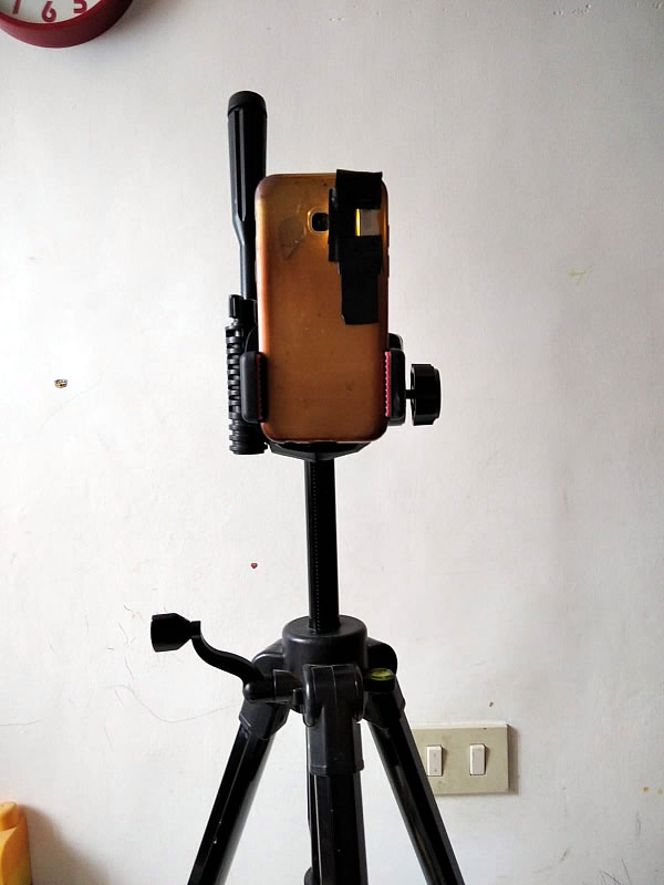
Returning to the mirror and his astigmatism, this is what it looked like during polishing.
The video highlights the arrangements of the two radii of curvature that determined the asymmetry of the figure, (with “R+” the shortest bend radius). The mirror was therefore placed in the position of maximum deformation , with the spokes at 45 ° with respect to the slit, because with the ray “R+” or “R-” parallel to the lattice-slit the resulting figure at Ronchi became regular in both cases.
Beyond astigmatism, different local irregularities that the step of grinding with tool al 50% she had evidently failed to standardize.
Now the mirror is on the mend, still convalescent with a small residue of peripheral astigmatism but which should conform without great difficulty. Is’ The technique described by Jean Marc Le Cleire in the extract excellently translated into Italian by Giulio was applied, which you can find some posts above. Some variations to this methodology were necessary to adapt it to the specific case, which in some respects was different from that treated by Le Cleire.
The reticle is hand held, therefore you will forgive the lack of fluidity and stability of the movement ( the ronchi-telephone is still experimental
) but it is important to see the action approaching the fire to verify that there are no changes in the inclination of the bands, at least in the central area, always in the position of maximum deformation.It can be seen in fact that at the edge of the radius R +, there is still an area with a smaller radius of curvature ( which expands and focuses first ) than the longest radius.
After this video, two more sessions were done with simple W strokes with a 21 cm, given that at this point it is not advisable to intervene on the entire quadrant, as the deformation is contained on a limited portion of the surface and not along the entire radius, as you can see well in the next video when only two to three bands are visible.
The defect is getting smaller, even if there is a consequent and foreseeable deepening of the center which must therefore be standardized.I believe that within a few sessions it will be possible to reach a uniform and regular sphere and begin parabolization.
-
AuthorPosts
- You must be logged in to reply to this topic.