Carry my positive experiment practical balancing the telescope Dobson, with the use of tension springs in replacement of heavy counterweights.
A Dobson telescope behaves in practice as a first class lever, that is, as a classic balance with two arms and central hub: The arm, We are saying A (see figure); goes from the primary mirror cell at the fulcrum of the lever coincides with the center of the bearings ” (in form semicircular)” altitude; and the arm, say B, that goes from this center to the extreme upper opposite, constituted by the trellis which ends with the case of the secondary mirror.
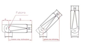
The balancing force requested, It increases with the cosine of the angle of inclination of the telescope, and is zero when the telescope is pointing to its zenith
Is’ This practice first-order lever which the fulcrum between the two opposite ends that represent the mechanical power and the resistance, which must be balanced in order to achieve a desired mutual balance, that allows the telescope to not move from the position aimed.
The balance sought precision is generally not critical, since there, for well-made telescopes, one underlying tolerance, always provided by the friction of bearings in elevation made with materials such as teflon sliding on rough Fòrmica "Ebony star" ... (or Teflon and other laminates "HPL" alias the ant Italian version with the necessary surface "sandy" type the print ABET LAMINATI HPL "minimum decorations n ° 236" or 563 catalog, and the like).
The recent escalation of projects towards ever lighter Dobsonian to increase the ease of transport, It involves the progressive difficulty of their balance, because, to lighten it man favors a very low primary case, so with the very short lever fior the "A" arm, that is likely to cause a moment of resistance no longer able to balance the powerful moment of the opposite side B of the balance, which is known to be given by the total moment generated by the sum of the moments of each component present on the B side of the lever. For example: trellis + Case secondary + secondary mirror and its support + focuser + eye + optical finder + finder type Red-dot or Telrad.
Today, not to encourage the balance also contribute the heavy eyepieces having large FOV, spectacular, comfortable and very powerful ... but much heavier than old eyepieces.
rule that to balance the weight of an eyepiece by 100 grams inserted in the focuser of a telescope with a focal ratio (for example) F=5, need to add “F times”, that is 500 grams of weight behind the primary mirror.
(In optics, the letter F represents the ratio between the focal length of the lens, divided by its diameter. For example, a telescope lens with mirror diameter 300mm and 1500mm focal length has a focal ratio of F 1500/300 = 5).
Every lightening the structure of dobson, ends then to determine the need for increased allocation of counterweights.
And we need this soon leads in front of the “nothing done” from the practical side, consistent to help relieve the structure ….for having to carry though with us so many balancing weights as it is high lightening operated.
Perhaps the only technical solution that can not erase the benefit of lightening, It consists in the transformation of the counterweights (that they are in fact static loads), in dynamic loads provided by the traction springs, or elastic rubber (for the latter see here an example of lightweight telescope balance: https://www.grattavetro.it/ri-bilanciamento-dinamico-con-elastici-di-telescopio-dobson-light/), and in extreme cases to the installation on the telescope of a parking brake https://www.grattavetro.it/costruzione-dobson-light-300f6-con-freno-a-disco-fase-1-realizzazione/.
It's true that certain counterweights "extemporaneous" are easily improvise (In Saharan OASIS I used for this purpose my trekking boots, that with their long laces allowed to be hung on the scissor frame for binocular tripod). But you can do much better by transforming static loads in dynamics, to achieve equally balance of a telescope to hand carry, or shoulder in a backpack.
Many "experts" from overseas, for that reason, They have replaced the weights to the primary mirror with a pair of tension springs, one for the telescope. Mechanical Principle I saw also applied to the Sumerian European Alkaid, Although if adequate traction doesn't make the elasticity of a spring, but that of a rubber elastic.
The two traction springs acting on each of the two altitude side bearings (in form of "half-moon") of dobson, so that together they provide a dynamic force balancing, that It must grow with the growth of the tilt angle of the telescope.
HOW TO ACHIEVE THE TARGET PRACTICE IN THE BALANCE
Eligible springs are those of the type TRACTION (that is, with the spiral closed which makes them "preloaded" and extensible more efficiently that spring in compression type that have spaced coils (not suitable for this use).
The springs require a force directly proportional to their relative elongation.
But to balance a dobson requires that the balancing spring force is zero or minimum when the telescope is aiming at zenith, and go increasing up to the maximum thet you will have reaching the horizontal position of the telescope.
And this growing trend reflects faithfully the grow of the cosine of the pointing angle ... As, in simple terms, we recognize that our cosine angle is represented by the horizontal Axis screening of its carrier, that grows in length (i.e. in foce) as you tilt the telescope, as shown by the previous image.
Each spring is connected at one fixed lower end of the "rocker box", While the end mobile is connected to a steel cable that reaches the extreme of nearby half moon/altitude bearing through the interposition of a deflection pin or pulley.
The pin or pulley interposed, and its diameter (that the smaller and more grows useful resistance) has the aim of sending back the traction so that it forcibly may grow with the growth of the cosine of the angle of inclination of the instrument.
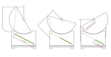
The tensile force of the springs on both sides of the telescope, is zero in the right image when the telescope points to the zenith, and increases in the leftward images, with increasing inclination, according to the increase of the cosine of its angle
Each of the two springs (in Green on the image) installed on both sides of the telescope, It will take charge of half of the total weight to rebalance.
For better understanding I think is useful to expose the practical application on one of my dobson later at a change of a heavy Hubble's mirror, with one lighter.
In the first instance it is necessary to mount the instrument complete with all hardware observation that affects balance. And then what did, It must be take over in practice by placing weights, How many kg of counterweight is necessary add behind the primary case to retrieve the general equilibrium.
In my testing, I found that served 2,3 kg.
Each of my two springs would then oppose a "traction " up to (2,3/2=) 1,15 kg
Taking now into consideration the RADIUS altitude bearings, which in my case they were 260mm, I decided that I could exploit so useful 240 mm of that length, for attaching the end of the cord connected to the traction spring.
(However, all along this stretch of 240 mm would have had the possibility of "match" (equalize) the right traction, by moving back and forth his fixing point, thereby being able to vary the length of the force "arm", and assure the achievement after work, of a very fine adjustment of the desired balance).
Then, the strength of 1,15kg divided by its "arm" of 240mm, gave me the strength that the adequate spring must possess (The relationship between stress and elongation is in fact technically called stiffness of the spring) ie more or less (1150g/240mm= ) 4,8 grams per millimeter of elongation.
This meant that the appropriate spring, loaded with a weight of 100 grams, you would have to stretch to about 20, 8mm ... or loaded by one kilogram would be lengthened by 20.8 cm:
The second and last practical parameter to detect, was the maximum extension that was supposed to reach the suitable spring (Lmax), without deteriorating when the instrument are passing to aim from zenit to the horizon.
The elongation must is obtained by measuring the distance between the center of the return pulley, and the terminal anchor the cable to the bearing of altitude, during the telescope inclination from the zenith to the horizon.
These three figures are the minimum necessary to successfully run a balance.
With these last two pratical parameters, the builders of the springs (as well as provide us springs with terminals made in ring shape, centered on a diameter of each coil-end of spring, as it is convenient for this use), are able to determine exactly that last.
Indeed: With the extension you want, the vendor can determine the optimal coil spring diameter (which, if is more smaller in diameter and more and short would be the spring life, because too strong short-Twist) ; and with the unit load, can determine the diameter of the steel wire that will use taking into account the shear modulus G harmonic steel in use.
If the springs are not supplied by a manufacturer, but, for example, bought in a DIY store, things are a bit 'more complicated by empirical compromises that you have to find along the way, placing springs perhaps in series (in order to achieve substantial elongations) or in parallel (to increase the strength).
In these cases, to wander in the environment, must be the "eye", and for that is necessary knowing the general "thumb" rules of construction regarding springs, which are as follows:
Typically the diameter of the wire of the springs (that make the case of balances of dobsoniani for few pounds), is between 1 mm and 1.5 mm.
Therefore a second technical insiders rule determines the diameter of the coil of the spring took at center of the wire, equal to ten times the diameter of the wire.
But the manufacturer can vary the diameter of the coil, in function maximum attainable elongation.
In fact, the larger the diameter of the coil and the smaller the solicitation to twist on Spring wire,, for not going too close to the limit of elasticity in torsion, and adversely affect the life of the spring.
Normally an extension spring is designed to be stressed in extension up to 2,5 o max a 3 times its length at rest.
In my telescope I wanted springs able to lenghthening by 380 mm to exploit the most of my arm lever 240 mm (on the 260 radius of altitudinal bearings) and they had a stiffness 4.8 grams / mm.
With these input data the supplier calculated and provided the springs wire diameter 1.2 mm, each 150mm long and with an outer diameter 12mm.
This means that all the work can be done in a practical way, no need to prior make calculations.
However, for those unwilling to deprive yourself of the pleasure to be derived data, formulas stiffness and of extension of the spiral spring are the following, where :
G It is the modulus of elasticity in torsion (depends on the quality of wire, but it is typically about 8000);
D It is the diameter of the wire;
r is the radius of the coil measured on wire Centre to wire center
stiffness = Π • G • D wire ^ 4
Extension = Stiffness / (32• radius coil ^ 2 • Spring length mm)
The’extension indicates Kg needed to compress or stretch of 1 mm a spring
Anyone wishing to explore can find a fine article by Tom Krajci of Sky and Telescope November 1999 page 130 “A balancing act for dosbsonian telescopes”