PART ONE, of FOUR:
This work is made transcript (I hope) readable, relative to notes taken in pencil in my “"grattavetro" Diary” during the construction of the mirror installed in my lightweight Travel Dobsonian Telescope, in photography.


Notes that are usually taken, for myself, because, as time goes, on the activities that you not do every day, You forget some important steps, as well You forget many dangerous attitudes that lead to avoidable errors.
Rereading in the times some steps of my writing, myself have benefited, making several times that path (with some mirrors) with "no serious damages".. The work described does not include the excavation of the curve on the glasses mirror and tool, that was made by machine from the supplier of blank and tool.
You might infer that the mirror 250F5 in 29 mm thick in float glass would be fine constructible, using this economic and commercial glass but that have a maximum commercial thickness 19 mm . But I discarded that possibility because its light weight in 19 mm thick, I still would have exacerbated the problem of balancing, due to the great lightness of the whole primary mirror case, of this telescope having structural weight of only 8 kg scarce, in comparison with its beautiful opening diameter.
Then I have ordered a blank in specific thickness 29mm , that was the maximum projectually thickness (and maximum desirable balancing weight) compatible with the construction of the hand luggage measures format “"cabin" model for carry-on plane.”. And then turn into a kind of dynamic counterbalance the surplus taken to the secondary to balance, realized with the traction of rubber elastics. the excess of weight due to the use in this telescope, of modern but heavy wide field eyepieces., having 1″1/4 barrel..
MY TECHNICAL DIARY (By nature I am far from the consideration of psychological journals. This fact is not, it is a substantially technical guide).
The blank had a diameter Pyrex 255 and thickness provided on my specific request equal to 29mm, while the tool measuring 255x19mm float glass (calcium-sodium). Both purchased in Italy, including the radius roughing service 2500 mm (Service costing 35 euro, year 2008).
So provided already machined with a surface curvature and arrow (concave for the mirror and convex for the tool), of 2.92 mm. Including bevel the edges with width of approximately 3 mm of its flat face at 45. degrees, that its large in orizontal sense was (3/root 2 = 3/1.41 =) 2.12mm.
Then at the moment of start working, the presence of the chamfer reduced the useful diameter to (255-2×2.12=) 250.75mm.
In fact there was no worry because this chamfer would greatly narrowed for wear during processing. And the end result would be a useful mirror with definitely diameter not less than 250 mm.
NOTE ON THE ROUGH GRINDING AND UNIFICATION OF CURVATURE IN MANUAL MODE
Having bought the blank and tool pre-excavated to the desired depth of mirror center arrow, (corresponding to the radius of curvature of the desired focal lenght), It is an advantage that save athletic work roughing manual of the initial sphere, and the work of unification of the two surfaces tool and mirror.
Unification which is indispensable, because the reaching of the depth to the arrow center mirror obtained with manual processing, is usually a phenomenon very localized at the Center mirror, It therefore does not match ever to having a good spherical surface.
And this is made visible by the fact that typically manual processing leaves completely intact an peripheral annulus on the mirror of at least 1 cm; and also a circlet in center tool with diameter some few cm , equally intact.
Both the Circular annulus and the Center intact, They are clearly visible from persistent central air bubble, trapped between the two overlapping in processing glasses, among which water is present and abrasive.
Normally so, with the achievement of the central arrow, ends the so called roughing step, and began that to unify the rdius of the two surfaces tool and mirror, applying no longer chordal strokes that are efficient during excavation, but those 1/3 Diameter, center over center (c.o.c).
These strokes 1/3D c.o.c applied by turning around the table, and rotating the glass that holds under the rule of their use, are important because, not exceeding in left-right direction,, is guaranted the obtaining of a sphere without need to make measurements.
From the test perspective, mistakenly you think that it serves one spherometer to verify the achievement of the initial sphere. But in fact it is useless, as it is enough to see what happen in the course of working with 1/3D strokes, Central air bubble between the two glasses should be gradually reduced until it disappears.
When the air bubble between the panes is completely disappeared, you are sure that the two panes (concave mirror and convex tool) They have reached the same identical radius of curvature, or you have obtained the desired sphere, and you can start the work of progressive refinement of surface quality, with abrasive grit away finer way. And the test will start only when polishing which follows the refining surface are in advanced stage to make reflective his surface.
CLOSED NOTE ON ROUGH GRINDING AND UNIFICATION OF CURVATURE IN MANUAL MODE.
We come then to writing in “in the present time” as recorded in the diary:
Check which focal lenght corresponds to the 2.92 mm center "arrow":
bending radius corresponding = (Diameter / 2)2 / 2 Arrow = 15625 / 5.84 = R 2675 mm,
Focal curve = R / 2 = 2675 / 2 = Focal 1337.5 mm
Focal ratio or F number = F / D = 1337.5 / 250 = F 5.35
Instead the nominal arrow of a mirror diameter 250 and focal 5 times the diameter should be:
Arrow = (Diameter / 2) 2 / 2*R = 3.125mm
The arrow 2.92 presented by my blank is an asset that is slightly less than that 3.125 definitive, since during the processing it will be inevitable an increase, that will keep it until end of work (except drawbacks) very close to the nominal value corresponding to the ratio chosen F5.
FOR THE CONSTRUCTION OF THE MIRROR I EXPECT THEN WORKS LIKE:
- SMOOTHING to bring surface roughness at the level of the abrasive grain 800, taking care that the arrow remains near distinctive 3.1mm relationship F5, and taking care not to cause defects zonal and astigmatism.
- POLISHING order to obtain a perfectly reflecting spherical surface as the free surface of a liquid surface.
- PARABOLIZATION to countersink the spheroid obtained, up to ensure that the difference between the radius of curvature of the central zone and that of the edge zone reach 1.95 microns with the progression of the reference parabolic curve.
If interested see the following demonstration in italics characters , otherwise skip this cursive script.
|
Demonstration of “depth parabolization” as the difference of the abscissa at the edge of the mirror with respect to the center, from spheroidal and parabola curves: We must refer to the following figure and its Cartesian axes of the abscissas (X-axis horizontal) and the ordinate (vertical axis Y). On these axis we must overlap on a parabola with vertex (0,0) and Y equal to the maximum radius of our mirror, a circle of equal radius, that in this point (0,0) will share his third quadrant (counted hourly Convention). For this to happen this circumference will have to have the center to the coordinates (R,0). Recalling that analytic geometry from the equation that describes a parabola is:
Let the symbols of the actual values, and in our case: R is the radius of curvature dug in the mirror (2500mm); Y, It is the ordinate (vertical) we want it to be equal to the outer radius of the mirror (125mm), (being (0,0) the center mirror, in our example coinciding with the vertex of the parabola); and finally X is the unknown coordinate of point Y, on the horizontal axis. then we calculate the value of X for the parabola, which appears to be 1252/2•2500= 3,125 mm. That is the center of our mirror to the outer edge (ie at the distance of the radius 125) there is a difference in depth of 3.125mm. Incidentally this is also the (method and the) value calculation of what is called ARROW, that is, the maximum depth of the parabola we are interested in getting digging the glass. Let us now see a circumference which would be the ARROW at the same distance above view.the equation that describes a circle with center (R,0) is:
from which with a simple passage that is located :
The symbols have the same values already seen. Then we calculate the value of X which identifies the similar ARROW (freccia) circumference, and find: 2500- root (25002-1252) = Reminiscences mathematical remind us that will be derived from the root two terms: one negative and one positive. We of course take into account the absolute value that allows us to accomplish the desired removal in the quadrant for a desired: And from what we get that 2500- root (25002-1252) = 3,126956 mm Thea difference between the two values of X found for the circumference and found for the parabola is then = 3.1269557 – 3.125 = 0,001956 mm that is 1.956 microns
In conclusion, to get a parable F5 from a spherical cap with a radius 125 like ours, we need to countersink the sphere with a maximum at the edge of the mirror 1.956 microns End of the demonstration |
 it can be deduced with a simple passage that :

The question of the hour is: With what size of abrasive grain do you start??
We should start with a slightly finer grain than that which already created on the rough blank, but it is unknown .....
How do you then know what are the dimensions of the craters produced by the various grains?
Born there WEB, Neither the "TOMES" (sacred texts); I studied to tackle the job, report specific suggestions in this regard.
Texts that are:
- The construction of the telescope amateurs Jean Texereau;
- Realize your telescope di e Karine Jean-Marc Lecleire;
- Amateur telescope making vol: 1, 2, 3, Albert Ingalls;
- The dobsonian telescope di David Kriege e Richard Berry)
Only a little table i reaced on the book (2) to page 81, showing the average size of various grits, emphasizing that even though each abrasive provider has a different range of sizes that populates each grain ("grit") nominal.
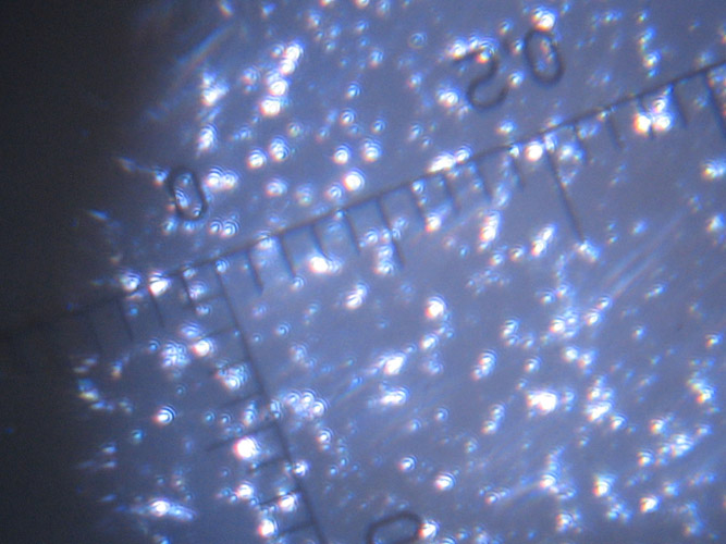
Since the latter statement is an implicit invitation to distrust of the table, I decide to watch it myself under a microscope the size of craters left by rough grinding on the surface of the mirror, then to compare them with the size of the grits ("grit") abrasive in my possession, purchased with the mirror and the tool.
then I look at the surface of the mirror blank, with a small portable microscope 30 magnifications (costing less than 30 euros on the stalls of the Russians, but now also on the Web), with grazing light, even with grating lens, with 0.1mm divisions, and I see craters 0.3mm.
So I think by analogy …assuming you have to destroy a wall with a hammer, the vast majority of debris produced should not be larger than the hammer used ... And so I convince myself that would seem equally likely that some abrasive grains ("grit") are lasting mainly craters with size up to the size of their grit.
Surely there will be more craters exceptions, but they will be few and due to fly out of scale "deaf". That glass cracked peninsulas, that they remain attached to the rest only by a small peduncle, which at a certain moment breaks, and jump off.
I look too different grits in my possession and transcribe their average size on plastic containers.
(Upon arrival abrasives were packed in cellophane bags, I poured it in white plastic containers typically used for chemical and biological liquid storage, from 0,5 liters capacity, with inner capsule cap and overlying the external cap screw, of those with any hole for exterior sealing. See image this Article All you need to “Mirror Maker”, ( that means “GRATTAVETRO”.).
My abrasives are the following, all in carborundum:
| Q.ty (g) | grit size |
Grain (mean) size (µm) |
| 500 | 120 |
100 |
|
300 |
180 |
50 |
|
200 |
320 |
35 |
|
200 |
500 |
20 |
|
150 |
800 |
13 |
- a whetstone for chamfering and medium-grained
I then have the following arasives required for polishing:
- 250g of zirconium oxide with less than the grain size of 0.5 microns
- 150g of "Opaline", which is refined cerium oxide
- 1Kg of Gugolz optical pitch type #55
- 250g of Cerium Oxide
- 2 Rosin kg of flakes, that would be the famous named "Greek Pitch", substitute reddish much cheaper than pitch black.
Returning then to the choice of the grain with which to start work, I see that the closest in size to the craters is the 120, and then I decided that if I have to improve the surface must certainly use an abrasive grain size smaller than the size of the existing craters; and observe that the abrasive immediately lower for size will be more efficient than those craters, which in my case it is the grain 180, although less aggressive due to its smaller size it requires more work.
then start the polishing work on February 1 2009, starting with abrasive 180.
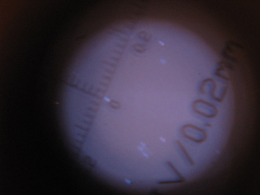
Crateri from the 50 and 100 microns (the minimum division readable in this microscope is 0,02mm )
The workplace is the boiler room / laundry room of my house.
The workbench has long been prepared and consists of a empty metal drum 200 l (one time containing mineral oil), I removed the cover to chisel, cleaned the inside, retorted the roughness of the cut, For ballasting it so it does not move during the process, I chose normal bricks (11,5x6x25 cm weighing each 3kg) of which only one layer on the bottom of the drum, it requires 25 for a weight equal to my body weight.
(See images in THIS article titled " All that needs to the “Mirror Maker”, ( that means “GRATTAVETRO”)
The drum I then built a lid with two tables of plywood 15mm thick. overlapped joined with screws, and resting in the interlocking of the stem opening.
The bottom of the cover disc is of such a diameter as to fit right into the mouth of the barrel. The external drive (the real work surface) instead it is of greater diameter to lean against the stem on the entire perimeter.
The working surface of the table was covered with a carpet in Foam perforated (of those who buy such a meter at the supermarket), also in turn covered with some intersections of transparent film from high packing 60cm (but it is also fine the blacks bags of garbage and cut open). Finally an elastic hook type for those with luggage car, He keeps the whole.
With the same plastic film sheath also the surface of an ironing table, I care about his notebook gauges etc..
For the moment it is not necessary to use the three wooden latches to 120 degrees to prevent the movement of the mirror / utensil on the table. And much more convenient to have the work plan free and then I use a simple clipping 30x30cm thin perforated plastic anti-slip shet, which it is also very grippy to the touch, (you buy in the supermarket DIY homemade department), held at the center of the table by four pieces of packing tape.
Taken the abrasive container and removing the cap the external screw, I drilled (with the pliers to pierce the pants belts) the inner capsule, with three neighboring holes, all made in a row on the same side.
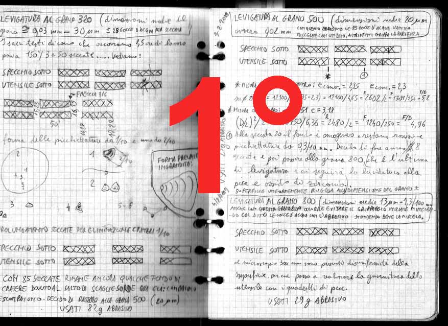
Dusting abrasive than a simple tilt of the container comes out well alone by the three holes, and I see that My "wets" of work (NOTE: BE AWARE fron translation in english, that in italian, couriously Wets of mirror making works are named "dried". and the authomatic translator can keep mistakes) are going better if I put only 28-30 water drops (more water carries away immediately the abrasive without allowing it to work). An unused old oiler does well by dropper, and drops the water where it is needed.
From the sound that fades as the third grain loses efficiency, known that wets last about 2 minutes each.
I ran my strokes (NOTE: in italin strokes is "corse", and the automatic translator mistakes its in "races") back and ahead width 1/3 diameter, and right and left 1/8 diameter: In practice I stick the edge of the object which in turn is in my hand (mirror or tool that is), of 4 cm forward 4 back for a total of 8 cm (that is 1/3 Diameter); and I do extend 1.5 cm right and 1.5 cm to left...but now I realize that it's easy to overdo it in right and left, and it is dangerous because it leads to inadvertently generate a figure no longer spheroid but flared over the parabolic shape, which it is to be avoided. Worth the hard work to return the curve to the sphere.
In light of all that, I decide that, while working, this left-right amplitude I must think equals to ZERO. And with this device I look automatically that it comes just over 1cm in each side, that is good..
Since blanking carried me, an arrow almost final, I decide to proceed immediately my wets with alternating mirror under and with the tool below.
Impressing the movement, I do not apply any pressure force, but only one necessary part of the shift in my hand.
Towards the end wet describe a circle to redistribute the residual abrasive.
In order to separate the disks at end wet I run them without lifting.
The rhithm is about two go back n' forward per second.
Keep My hands on the edge of the object of preference (mirror or tool that is) well taking care not to add weight.
I turn in small little steps around the table slowly clockwise, and it rotates the object in his hand constantly in the opposite direction to my steps, a small fraction of a turn at each round trip.
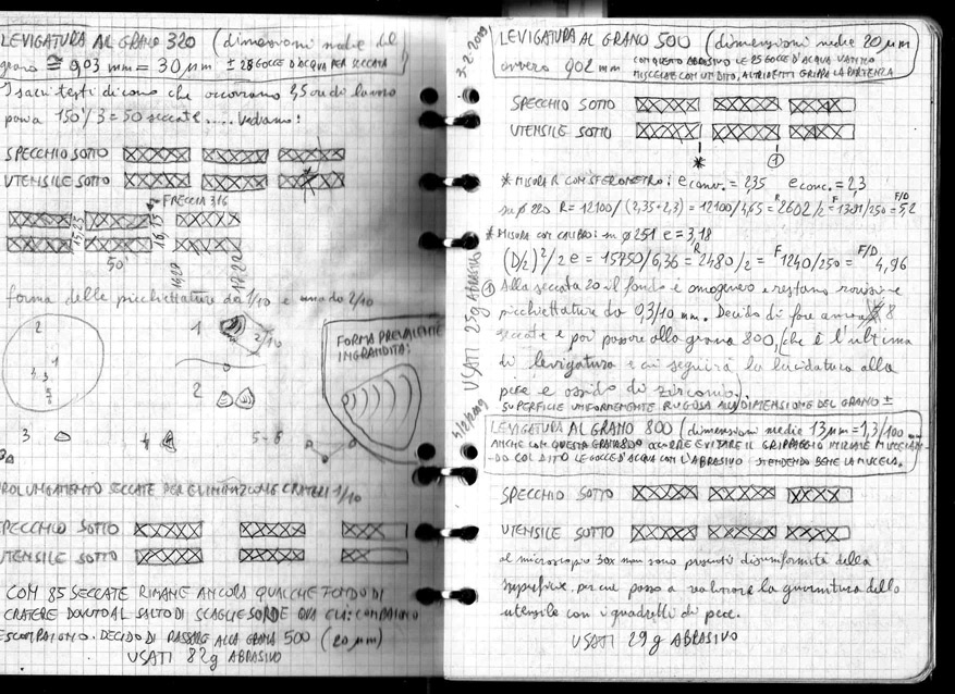
Inaugurate the checkered diary to record them as I go; Then write on two lines of notebook , the working positions "mirror under" and "tool under", and in the row of cells to the left of them, I point the wets performed with the vertical rods ... but soon I realize that if they take the work stoppages, there is the case that the recovery I do not know more what should be the next working position.
To gain a clear indication, I decide to replace the rods with the X marked in two-stroke: Sign that is the beginning of a wet with a single rod diagonal into the square of the paper corresponding to the position in progress, and complete the X after the end wet, adding the slash in the other direction. Simultaneously with the completion of the previous, I will sign a new slash as the beginning of the next wet in the other position (see figure diary with the X rows "Specchio sotto" or "Utensile sotto").
Every 10 werts I measure the arrow (see deep at the center) to see if it moves.
The rules of the game by using amplitude strokes 1/3 diameter, are few and simple:
- To deepen the center (until the 70% diameter) not touching the edge, You must put the mirror above the tool (Mirror On Top)
- To deepen the edges (from the 70% diameter onwards) not touching the center, You must put the mirror under the tool (Tool On Top).
- To maintain the arrow you must switch between these two locations
It should be noted that the strokes 1/3 Diameter are inefficient for luck in abrasion which determines the variation of the arrow. Therefore it is necessary to achieve such depth with the coarse abrasive grits, otherwise with those more up fine grained you may be unable to achieve the desired arrow, thus obtaining a telescope with a slightly longer focal length of the desired.
My fear in this moment is that the arrow can vary due to the difference in weight by a third, between mirror (29mm thick) and tool (19mm thick), and then difference in efficiency in alternating work.
To think finicky, you should load the tool of a ballast weight equal to the difference ... but I decided to "not bandage my head before to break it" ... and I proceed.. Checking it well on the way.
To measure this arrow, individual and mark the center of the mirror, with a small dot marker (done through a hole in the center of a paper disc of diameter equal to the mirror and is superimposed thereon).
I put a mirror along the diameter from 25mm profiled framework aluminum as a kind of ruler, and using a digital caliper (previously reset to the measurement of the thickness of the ruler that is 25mm), placing it on the ruler, above the center mirror, to lower its sliding depht probe to touch the dot.
In the work I look in transparency from the beginning, that during the wet, between mirror and tool in contact with the abrasive wet interposed, there is no air bubbles. A sign that the two concave and convex curvatures are perfectly identical.
And I also see that the opaque stain wet abrasive widens gradually between mirror and tool with the progress of the wets and reduce noise, rotating with the manual rotation that impress with each pass, and that gray smear of abrasive that is working widens until it reaches the edge of the object that is on the table, which becomes opaque from transparent. All without ever smearing on the table over the mirror edge .
This is a signal that the amount of water is right, and that the abrasive is in optimal quantities to deplete its function.
I discovered that in fact putting an excessive amount of abrasive decreases the efficiency of its work, is likely due to the abrasive grains that are more easily in touch with themselves rather than with the glass to be removed, destroying themselves and their abrasive capacity, without removing more glass than a smaller abrasive amount.
Note the benefit of those who were to read an English translation of this article: in America quel che io definisco “passata” è chiamato STROKE = colpo; mentre la “Seccata” è chiamata WET cioè umido…….Questione di temperamento!),
Later, after 60 wets almost completely disappeared signs of roughing.
The arrow does not move appreciably.
But I decided to gear up to see better the elusive craters. Then I put a glass shelf (5mm thickness) leaning between two stacks of encyclopedia volumes.
The thickness …..cultural "given by’ encyclopedia, supporting the glass shelf and the mirror with the microscope leaning over, It allows me to insert under a portable lamp 40 watt, in order to vary the inclination and the lighting while I explore the surface of the mirror to 30 magnifications.
Looking in this way see definitely better than the larger craters has now approximately the size of the abrasive grain 180. Sign on the edge and on the back of the mirror the reference to the position of two of them oddly shaped and decide to do even a dozen dried to further control what happens.
After work, I see that one of them is partially eliminated, but another neighbor was born. The grid of the microscope tells me that the craters measure is compatible with that of the current grain caused craters 180. And I decide to change and switch to grit 320.
Total: 70 wets - grit 180 - Average grain size: 50 microns – work time: 3 hours – Abrasive used: 71 g.
At the change of grit abrasive, must eliminate everything that you used with the abrasive previous, to avoid the danger of scratches caused by a single grain of coarse abrasive forgotten, runs unexpectedly on the mirror in the nexts works.
Then I replace all covers of the tables in plastic film, change the sponge used between a wet and the other to clean mirror and tool, the towel. Lavo I brush and thoroughly rinsing the basin of the sponge. Step vacuum cleaner non the floor.
(Following is the part 2)