Curvature Correction with Sub-diameter

We have seen in a previous article the general operation of the technique of strokes with sub-diameter. On that occasion, we examined the aspect relating to processing by identifying the zones or circular sectors in which the material removal takes place more or less effectively.
Let us now go into more detail on the effects that this process produces on the curvature of the conic that is being generated at the moment when we use the sub-diameter to make corrections in certain areas.

What in fact interesting to grattavetro is to know in advance as a mirror field will change its curvature as a function of a specific technique.
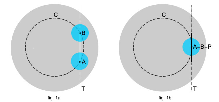
To do this we fix the first “degrees of freedom” processing ( fig 1a ), summarize ie in many ways and second directions and extensions such as the sub-tool it can be moved on the mirror.

  1. circular motion (-) relative to a diameter generated by the rotation operator ( or of the turntable )
  2. movement to and fro according to a secant T the circumference -
  3. extension of the stroke along the segment A-B the line T
  4. localized pressure at a given point P tool.
  5. constant tool rotation

degrees-lib

As we will see all the points highlighted affect the final result, in other words, the variation of the curvature on the surface of the work is determined by the combination of these elements.

SIMPLIFIED APPROACH

For convenience of understanding, first we examine a particular case that will help us later to extend the results obtained in general form.
With reference to Figure 1b suppose to minimize the displacement of comings and goings A-B up almost to equate the two points A e B, What, however, achievable only by moving the rotation tool above the mirror on a rotating floor, we also consider the increasingly localized pressure at the center.
This simplification in which the straight line T becomes tangent to the circumference C and A = B, It takes us back to the case in the general aspects regarding the excavation with sub-diameter and allows us to make some important assessments starting with an aspect already examined:

It will generate a circular crown with a depression at the center in which the removal of material will be maximum along the circumference passing through the tool center.

Thus generating a depression along the circumference and for an obvious consideration of the continuity of the figure generated, that we will:

  • the outer zone in this circumference will increase its curvature, while the inner one the decrease accordingly
  • The loop circumference C for the tool center unchanged will retain its curvature .
  • the overall extension of the correct areas is equal to the extension of the sub-diameter ( in this case that A,B=0 )
CORRECTION

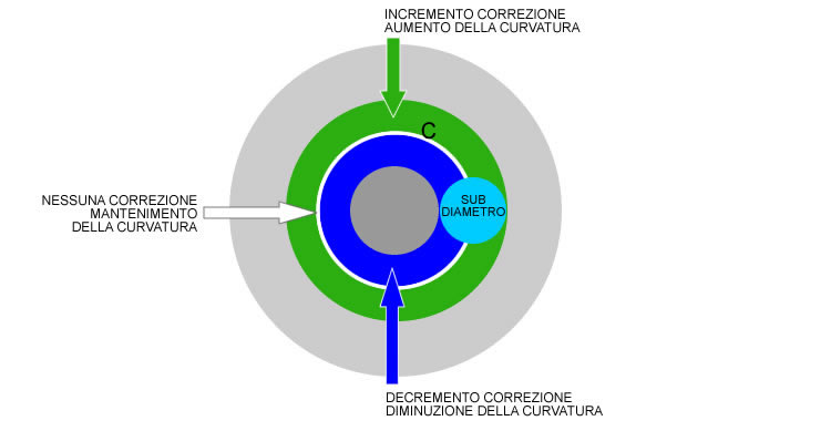
Fig. 2 – variations of curvature with non-extended strokes.

The increase of the curvature in a zone indicates that the correction to the radius of curvature will tend to decrease the value, in practice in this area the fire come “a bit’ before” compared to the starting fire, similarly in the opposite area the decrease of the curvature will tend to lengthen the fire, always compared to the values ​​before the correction.
The maintenance of curvature on the circumference passing through the tool center, It does not mean that the focus remains unchanged, but only that the figure will retain the trend departure, for example, if it was a spherical zone, it will remain spherical , similarly if it was already present an increasing tendency of the curvature, to find ourselves almost unchanged after the work session.
Then, in cases where the run-and-fro of the sub-diameter assumes very small values ( 1/8 or less sub-d, forward and backward similarly) we can definitely bring our work to this extreme case and take a circle through the center of the sub-reference tool.

GENERAL APPEARANCE OF CORRECTIONS WITH SUB-DIAMETER

If we introduce the extension of the broad movement of “and fro”, we derive the tool center intercepts the circumference - in two places A e B, while call M the midpoint of FROM .

CORRECTION1

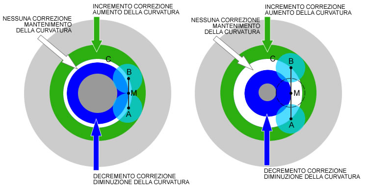
Fig. 3 – Variations of the curvature with application of extended racing.

Extending the reasoning for points A e B coincident, it turns out that the tool center, area in which the excavation has the greatest effectiveness, It will not move along a circumference but along a circular sector , in which the outer circumference limit is detected by the rotation of the outer between the points A and B ( if they are symmetrical circumferences coincide ) , while the inner circumference is determined by the rotation of the point M.

The consequence of this variation is the largest area of ​​the sector in which the processing maintains the original curvature, while the areas to over- and under suffer an offset correction and a reduction of area by reason of this extension, In fact, the different positions of the points A e B refer to the same starting circumference - the case of coincident points.

The retention of the curvature is, however, an effect “temporary”, valid in the case of fairly short sessions, with the increase of the processing time on the same sector is that of the tendency “level” the intermediate zone.

We will see more depth when it is most convenient to use short or long runs, for now we can say that the move away from the tangent of the base circle, or in other words, more we lengthen the races we move towards the center, more we tend to generate a spherical sector between the zones subject to correction.

SPECIAL CASES

In general, the most effective processing is the one that acts “the side” to the reference circumference, this does not mean that they can also be carried out central races or even the center of the center.
In these cases, the type of processing together with the constant rotation leads to making “stable” the intermediate zone between the correction areas in making spherical. In the event of a “pure” center on center with suB-diameter will be missing in the area under-correction which will be completely absorbed by the passage of the tool center.

CORRECTION2

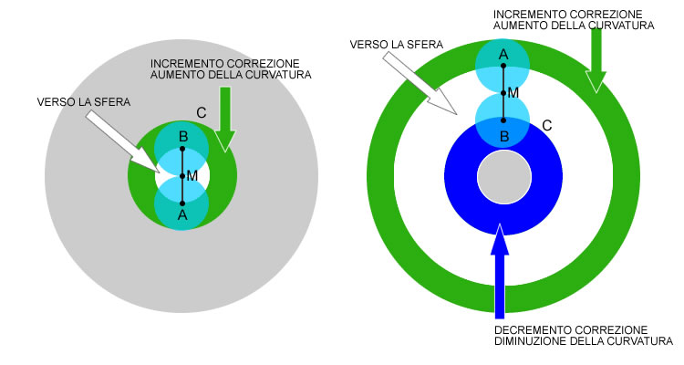
Fig. 4 – Examples of central races.

A PRACTICAL EXAMPLE

In this example taken from the processing of the primary Cassegrain, we consider this figure resulting from the Ronchi test, after the action of the sub-diameter in-hole close to the edge area.

Sl

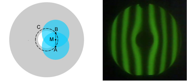
Fig. 5 – deepening technique of the center of perforated mirror.

This processing was performed with M tangent to the hole, right to create the central depth without a curvature area descending, namely a raised edge on the hole, also seen that it is not possible to completely switch over the hole with the tool, to be able to make a stroke the center must always rest on the surface.
The “hole” Central then had to be connected with the outer zones to continue to build the parabolic.

The technique adopted was to move along an outer circumference and identify the extreme points of the races on “edge” the sudden change of curvature, per “enlarge” The outer bands ( increase of the curvature – green Arrow, fig 6) e “tighten” what internal ( decrease of the curvature – blue arrow, fig. 6 ) to the reference circumference:
This sequence of images before and after a session of 30 minutes with a sub-diameter 120 mm.

es2

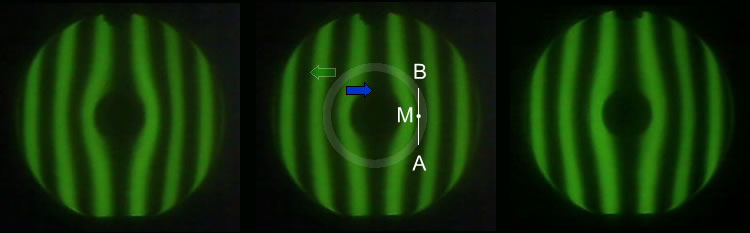
Fig. 6 – from the left: Figure departure, technique applied, resulting figure.

As you can see, the central hole is “spread” in a wider area. Continuing the action by moving to step outwardly to locate in the same manner the circular areas on which to apply the correction, the entire surface is possible to connect, to reach the desired figure.

CONCLUSIONS

two important considerations which constitute the fundamental preconditions for the use of sub-diameter:

  • Is’ always possible to increase or decrease the curvature of a single zone .
  • The sub-diameter allows us to intervene in both coarse so that with surgical precision on the surface and to modify the trend as a function of the tool magnitude of the applied pressure and the processing time.

we will see in subsequent articles that it is possible starting from these fundamental , get to build any type of conical surface you want to accomplish for our mirror.

Comments (13)

  1. Avatar

    Bartolomei Mirco

    Very Massimo, I do not know what I was waiting for this type of article. :yahoo:
    The correct way to use the sub-diameter for the correction of errors zonal I searched the net very, but I never found anything exhaustive and comprehensive.
    Question: let's say that in my mirror has only a raised hillock located about the 50% ray, having a radial extension of 50 mm. The tool must also have a dimeter of 50 mm? It must be greater? if you than you think?

  2. massimar

    massimar

    Thanks Mirco, :bye:
    Your first assessment I disagree, for minor corrections “precision” Also I would use a sub extended as the area to be treated by working with short runs and for a short time. This does not mean that we can not effectively use a larger or smaller.
    I think the best thing, at least until it takes place in an automatic way, is to design the intervention of correction by drawing it over a picture of the Ronchi or Foucault. I am comfortable with this system, in this way you can properly evaluate the tool extension and races required depending on the areas of Over- and under correct extensions.
    Imagine the picture of Ronchi Article, to add the outer and inner crown with the shape of the sub, and immediately displays how far will the fix bearing in mind that:
    – it is humanly impossible to get to and perfectly in a straight line, there will always be some margin of “heeling” which will tend to broaden the areas
    – the action of the sub-diameter in practice is always slightly lower than its extension ( This theoretically balance the slippages :-) )
    – If the patina is amended star, or at least reduced to the edges, this reduced action is even more pronounced.
    – the pressure also slightly higher due to, He digs like a dream, but it generates a roughness “concentrica” similar to the grooves of the old vinyl…

  3. Avatar

    Giulio TiberinI

    Hard to find a theoretical argument left to the intuition of those who “there comes”.
    Beautiful article Massimo!…The only reading is an incitement to try! :yahoo:

  4. massimar

    massimar

    Thanks Giulio, in fact it is rare to find references or feedback on this topic, It would be nice to compare methods and results, however my feeling is that these techniques are jealously guarded as a kind of “Professional secret”. It therefore becomes difficult any checks you write and what you have experienced, in the constant companionship of the doubt saying some nonsense too…
    In fact, I deliberately limited exposure to the part with a central pressure, I have not enough evidence to extend the argument to the localized pressure , but I'm working…
    I hope that those who will try to scratching with this method, can benefit from what is written, if only to avoid much of the “disasters” I have combined the first to figure out what was the right thing to do…

  5. Avatar

    Bartolomei Mirco

    One of the few sites where I found something that speaks a little of this subject has been on Astrosurf, in which, I think I understood, which in effect for the best use of this technique should exert a slight pressure towards the outer part of the tool and not exactly in the center. This is because since the surface of the inner annulus (the blue in the drawing) smaller than the outer (the green), the resulting excavation would not be symmetrical with respect to the average circumference “-” but it would be more excavated the inner part.
    What do you think Massimo, could be?
    In addition, according to you are valid movements to epiciclio replacing the rectilinear racing?

  6. massimar

    massimar

    Exactly Mirco, with the localized pressure we add a considerable precision instrument that allows us to distribute as we want the magnitude of the corrections to the curvature of the inside in the processing area, as I mentioned will be the topic of the next update on the sub-diameter, for now it is still under study & verification…

    It should be noted in this regard that in the process of correction we will often need to asymmetric processing, grattavetro the problem is in fact to correct a / multiple zones that appear to be out of tolerance, to do this will have to change once / curvatures, ad is. increasing them at the same time and decide where and how to distribute the complementary curvature descending without going to change the zones have already been corrected.

    Regarding the epicycles not know, so far I've only used them as a linking races, for a short time and lightly and frankly I have not yet understood the effects…

  7. Avatar

    Search topics

    Good morning, are in the final stages of parabolising a 300mm f4 (machine-made) and I find myself with a raised ring that I would like to eliminate… but I don't come to one… reading this article on diameter corrections it would seem to me that it could be right for me… this is the current situation.
    https://i.postimg.cc/VN3LXHPn/DFTScreen.jpg
    Could you kindly tell me which tool diameter to use and what amount of strokes to make? And maybe some advice (makeup) on execution (for example, how to stay in the desired races) since I've never worked by hand… he has done everything by machine for now.
    Thank you 1000!
    Giovanni.

    • Avatar

      Giulio TiberinI

      hello John.
      I see you are doing very well with red laser interferometry a 652 nanometers high., and you're almost fruitful with -0,965 of K-1 of the definitive parable.
      I see from the graph of the error profile on the wave that you have attached, that for now the major defect still existing is that central relief. And I see that the ring you would like to eliminate is less important at the moment, not even being considered an error, since the height value is 0,1 Where , that is to lammbda / 10 within the range of better values ​​than lambda / 8 precision.

      I believe that as processing continues it could also increase in importance, as you get closer to K-1

      However if you want a perfect mirror, and if you want to take the risk of going further in a game over, (which is instructive to better juggle the subject) you will rightly also have to deal with the lowering of that hump of the ring internal diameter 184×252 its 300 in diameter mirror, probably working by hand and taking small steps. For this delicate step, I believe the best way is manual use (or more risky to machine) of a sub diameter tool.

      I believe that Massimar is the right person to suggest tool sizes, position and movements to be put into play, in light of what is indicated in the article you read.

      Congratulations anyway for the good job.

  8. Avatar

    Search topics

    Thanks Giulio for your suggestion. I'm just continuing the machining of the central part… and the ring actually continues to take an increasingly important trend. Just for info I am attaching the last wave front after machining in the center with a 100mm tool and target area 140mm…
    https://i.postimg.cc/257Bbgg2/DFTScreen.jpg
    I hope for help in removing the ring of which I have not the faintest idea how to proceed. Thanks again.
    Giovanni.

    • Massimo Marconi

      Massimo Marconi

      hello John, I agree with Giulio: A nice job to finalize by intervening on the mirror center, because even removing the raised ring would not improve the median area ( which is already good ) but you would stray from the parabolic shape ! as the connection between the various areas inevitably passes from the center and it would be very easy to obtain a depression instead of the raised ring that, connected with the "high" center, would result in an over-corrected mid-zone. A sub-diameter at this point in the machining might help, but it should be used with caution and knowing exactly how and where to intervene. However, if the setup you have used so far ( machine and tools ) led you to these results, I would think about it before moving on to another setup whose effectiveness and use is not yet known, but I would prefer to try to optimize the machining performed so far , since you are already one step away from a very good result. Maybe you can open a dedicated discussion on the forum in which to analyze the situation in detail and study a strategy. In this delicate final phase of such a promising work, simply saying “use these tools and do this” would not be a good suggestion !

  9. Avatar

    Search topics

    Hi Massimo, I just finished a stage to keep lowering the center… afternoon I do interferometric test and place it… I could open a discussion but it is not a simple thing since I have written all the notes “bad” and I would have to take it all back to get all the history… this I would have preferred to do at the end of everything. Let's see where I am with the next test and plan the next phase? By now I will be at 99% I think… the machine is very constant and I can proceed by 1% at a time. But I really don't understand where that raised ring came from!!

    • Massimo Marconi

      Massimo Marconi

      Well! but it is advisable to let several hours pass before carrying out any test after a work session and when the error to be measured is so small it would be better to do the tests the next day !
      I honestly don't see it as a raised ring, the wave pattern of the profile is normal ( we are talking about two tens of nanometers of glass to be removed from a small sector ),
      if then this undulation, is within the tolerance zone is also irrelevant. The mirror you made, with a small correction in the center, it will be great but, I think it would be okay already ! :good:

  10. Avatar

    Search topics

    Hi Massimo… i just took the test… since the room where I work and test is the same and is air-conditioned, and I wash the mirror at the end of the process with water at room temperature I saw that after a couple of hours there is no difference compared to doing it the next day… however I always wait 4 5 hours at least… for example the test was done at 17:00 and the processing finished at noon so I'm very sure of the result. This is the wave front after 12 minutes of parabolization by machine with a 100mm diameter tool and 140mm target zone. I basically brought everything into the minimum tolerance and practically got to k-1. This is my first mirror (ever)… never worked one by hand and by machine and for a 300mm f4 I can be satisfied already but I would like to improve it further anyway…

    https://i.postimg.cc/05LTvbZv/DFTScreen.jpg

    I hope to receive some advice on this.
    Thank you 1000.
    Giovanni.

Leave a comment