ITALIAN TRANSLATION OF CHAPTER 8 DEL LIBRO "CONSTRUCTION AMATEUR TELESCOPE"
Jean Texereau
(NOTE: For French speaking readers, it is advised to read this article directly on the book he also took again, (pages 137 – 149) to avoid mistakes due to the double automatic translation).
The main difficulty of the construction of a telescope in a combination Cassegrain or its variant, It is due to the secondary mirror that is convex, and consequently it can not be controlled with the Foucault method without the use of expensive instruments such as auxiliary optical components, since the Foucault test is applicable only on mirrors or concave optical surfaces.
—————————
N.D.T: The only exception, however, the strange test applicable in direct mode according to the method proposed in 1945 J. H. KING, described in the edition 1998 Book A.T.M. 1 page p. 321, B.14 chapter "Testing convex surfaces" according to the following figure B.14.1, which consists in installing the convex mirror (or plano-convex or bi-convex lens to be tested), in such a way that it closes with the convex face facing the ambient air, a cylindrical tube-tank of given length by the radius of curvature of that face, that will be filled with liquid having the same refractive index of the glass under test. the opposite end of the cylindrical vessel will be closed with a glass optical window that is perfectly flat even if only on one surface facing the environment external to the tube. Optical window that will ensure the ability to run through it a normal of the inner concavity of the mirror Foucault test (o alla lente) viewed from behind, having the liquid of equal refractive index of the glass, rendered invisible, and in fact physically eliminated each reflection from each surface of the intermediate optical path immersed in it, with the exception of extreme convex surface, view that shows concave posteriorly.
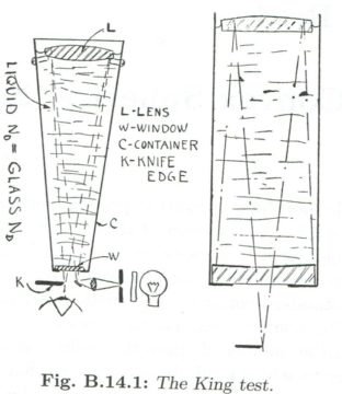
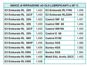
The generally small size of these mirrors do not oblige to large watertight containers, However, the complication of this direct test is finding a security filling liquid nonflammable and economic that has a identical refractive index (but probably just as close as possible) to that of the glass in question, knowing that the index of the glass start from that of the Crown (BK7) with value 1,5, and climb to normal calcium-sodium glass 1,57, up to the dense Flint glass with value 1,68. The most common transparent liquids that come close enough to those values, are turpentine and mineral oils, as you read about the image above, that is one of the images attached to the instructions of refractometers for industrial use for the verification of the quality of mineral oils, as reported by the figure above.
End of the note
—————————————————————-
Since the choice of greatly influence control method the entire course of the work, we will examine the four practical methods valid:
74. CONTROL“STAR TEST” ON THE WHOLE TELESCOPE ON A STAR(see below 82 A).
This method is applied in the normal use of the telescope with a bright star. It is assumed that the full telescope is available and mounted in equatorial mount well stationed and then moved by good clockwise motion with the primary mirror already ok and aluminized; While the secondary on study it is not essential that are metallized.
It takes a great deal of experience to correctly interpret a small defect through the star test, which is the Foucault method practiced visually on a true star;
This is because the turbulent currents of air make it an illusion that the operator must carry out the photometric equalization on the shadows of the Windows screen of Couder. You could integrate these vortex simply taking images (Foucault-grams) formed by a few minutes of photographic pose, but the digital count on images would be laborious since it would require the taking into account of all easement of photographic photometry. For these reasons it is preferable to use the method of Hartmann (2), photographically operated on a bright star as Vega, that would be shooting two images extrafocus separated by a known distance. In that way you would be able to record tracks “light brushes” or isolated light beams by a screen placed at the mouth of the telescope, and it would be sufficient a about one minute with medium sensitivity film exposure time, Although if only one of the mirrors is aluminized.
To measure the distance between the images of two bundles of light o a same area you need a micrometer that can read the micron; since it also knows the axial distance which separates the two images, it can easily be deduced the distances of intersection for each zone, even with greater accuracy and safety than that which would result from equalization made visually, on the Foucault test windows.
- Application details in the work method Hartmann are given in the book "Lunettes et telescopes" by Danjon and Couder.
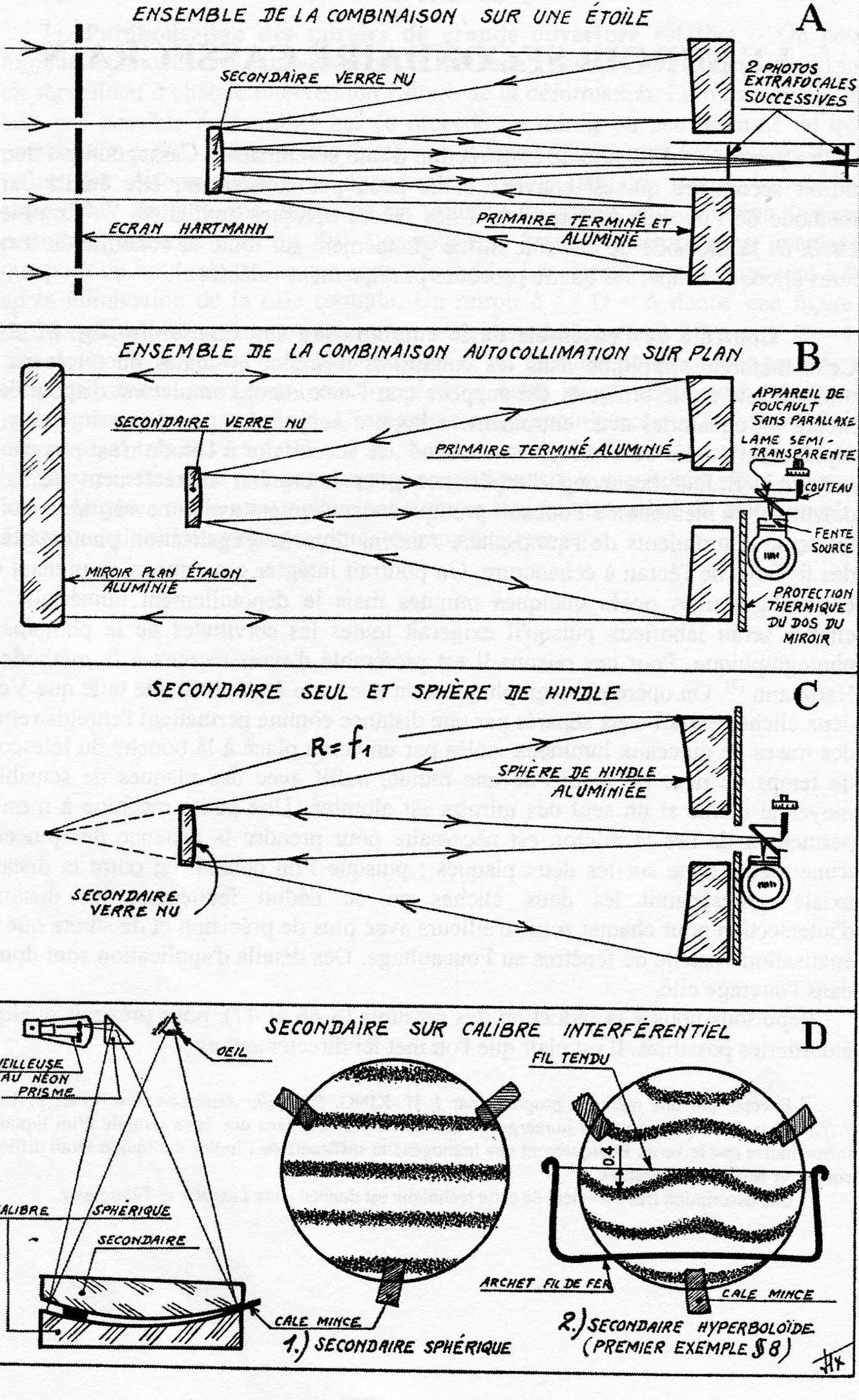
Figure 82
To avoid possible errors, it is best to freshen up a bit the ideas referring to the content of the chapter concerning the calculations for transferring the aberrations at the focal plane (reduction of aberrations at the focal plane), and at the chapter on the preparation of the inspection report or Check bulletin, as can be seen in the following figure 52 It comes from page 85 del Texereau.
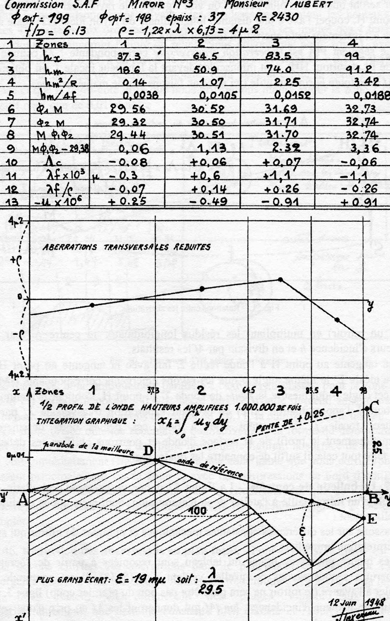
Figure 52 Control Bulletin
It is clear that in a trial with the source placed at infinity the aberrations are at the focus, and then you do not have to do the subtraction of hm² / R values in line 4 shape 52, which concerns the subtraction occurring only at the center of curvature, namely at the Foucault test whose source is not at the infinity, but also it to that Center, alongside the tester knife edge.
Similarly to quickly find the plane of the circle of minimum aberration, because we highlight the longitudinal aberration at the focus (line 5 fig 52), You must use the values of hm / F and not those of hm / 4F.
Finally, the transverse longitudinal aberrations will be found using the following formula (16):
The other bulletin calculations remain unchanged.
The advantage of a direct study of the telescope in the conditions of use, It is given by the automatic presence of the thermal aberrations involved actually, and that in a large telescope are often important .
Unfortunately, with the use of the star test, the controls and tweaks cycle remains subject to good weather forecast.
(The completion of a secondary Cassegrain diameter 60 cm for the Meudon Observatory asked us nearly six months using only this method, while at the Haute Provence Observatory a month was enough for a secondary diameter of almost 52 centimeters, for a Cassegrain telescope 193 centimeters).
In the case of a small tool you can avoid this problem if you have an enclosed and long enough room to be able to install an artificial star for at least thirty meters away.
The Visual Foucault test in that case would resume his lead since the air in the room can be maintained optically homogeneous, which it is not generally easy to get outdoors.
A small mask of Couder homothetic to the normal type, can be positioned against the secondary to achieve direct localization of the tweaks to realize. The source no longer at infinity would look with a slight over-spherical correction, and the longitudinal aberration would be much lower than hm² / R, but not necessarily negligible.
75. Control over the entire optical combination (that is, the complete telescope) by means of a plane mirror (see above in Figure 82 B) .-
Leon Foucault said that “a flat mirror for experimental optics is an artificial sky”. If you have a plane mirror without defects and at least a diameter equal to that of the primary mirror Cassegrain, you can use it for Autocollimation. This method has been followed by G. W. Ritchey in particular for controlling the combination of the Cassegrain telescope 152 centimeters of Mount Wilson. You will use a Foucault tester in which the source and the knife will be as close as possible, or rather completely free of Parallax using a semitransparent glass beamsplitter (Fig. 82 B). In fact, if the source is off axis, the symmetric reflections occurring are shooting our mirrors in substantially different points. We see that there are a total of five reflections, A first time the telescope with the source at focus, serves as a collimator for providing of parallel rays reflected from the flat toward the combination that becomes telescope.
Defects are then doubled.
You must alluminize the flat mirror and the primary to keep enough light. In the absence of a fully realized mechanic of the telescope, the Assembly must comprise of fine adjustments by means of screws agents on the three mirrors, and in spite of that, that collimation is a good exercise for a beginner.
This method, like the one above, allow to control only the axial beam.
The fraction that exceeds this secondary beam (if you want to extend the scope) cannot be whole controlled at one time.
Few amateurs, however, possess a good mirror of diameter equal to the primary plane. Good means that the zonal defects are annoying, but a small curvature of the floor is irrelevant to the auto-collimation.
76. Metodo Hindle (see above in Figure 82 -) (2). – You join the convex secondary mirror to check, to a large special spherical mirror test, whose curvature RADIUS is equal to the focal length of the primary mirror of the telescope. The distance d of the vertices is therefore the same in the real telescope.
This time there are only three reflections, and the beam passes twice on the secondary doubling so his defects.
The spherical mirror used in these conditions provides an equivalent stigmatic beam like this of the configuration of a paraboloid with a source at the infinity. The Foucault test thus reveals directly the secondary failures but doubled, as in the preceding method.
The measurements must be made with a small Couder mask , with the reduction of aberrations calculation as would occur with a parallel incident beam.
With a spherical mirror of Hindle a little larger than the primary mirror, you can control a secondary oversized for reasons of field.
The obvious practical disadvantage of this method is the need to build a second large mirror for each telescope configuration, therefore, the spherical mirror of Hindle is only justified for a production in series of standard Cassegrain telescopes.
(2) JH HINDLE “a new test for the Cassegranian-Gregory and secondary mirrors” in Monthly Notices by Royal Astronomical Society, March 1911, reproduced in A.T.M.1. page. 225.
77 Control a secondary on concave gauge (See above in the picture 82 D).
This method has been found and taught by A. Couder nel 1945-1946 the optical laboratory of the Paris Observatory. And it is also been discovered independently by J. P. Hamilton who published a good description in 1952 (1).
The chapters explain § 51 e 52 of page 93 del libro del Texereau, at about how you can run interference checks on plane mirrors with a Newton Interferometer easily auto-buildable D.I.Y, allow us to be brief
(N.D.T. See equivalent articles about interferometric Newton's testing in this blog https://www.grattavetro.it/interferometro-di-newton/ ehttps://www.grattavetro.it/frange-di-newton-concavita-e-convessita-delle-superfici-in-esame/ ).
It begins with a build of a small spherical concave mirror at least as large as the convex, and having identical curvature RADIUS r2. The verifying of the sphericity of this concave mirror with Foucault does not present any problem, We need only to be careful, with a mirror so small, the extra-axial aberrations in the telescope assembly, which can be troublesome if the source is not close or confused with the return image.
This spherical mirror will the caliber interference function.
If convex secondary mirror have a polished and transparent back (normal glass Saint-Gobain), the interference fringes can be observed by placing the light source and the eye close to the caliber center of curvature. Three paper spacers, of which one thinner, separates the two glasses, and as usual you have to steer towards us that thinner spacer.
If we assume that our convex mirror is spherical with the same RADIUS of the gauge, the interference fringes will be straight as for a flat glass (see above fig. 82 D1).
Note that the diameter fringe represents the section deformation of the of meridian of the controlled glass.
So whenever this deformation in relation to a straight line, reaches a inter-fringe, ie the centerline between two adjacent fringes, It deduces a difference Lambda / 2 which corresponds to 0,3 uM with reference to the wavelength of the effective wave of neon light given by the lamp used in the interferometer.
(1) J. P. HAMILTON. “A test for the secondary Cassegrain”. in The Journal of astronomicSociety of Victoria. February 1952, p. 7.
Especially if we want to ensure that the second is hyperbolic, enough to see if the central fringe draws well the trend in the following figure 76 II when the paper thin spacer (in the figure called "cale mince") It is positioned as shown above in Figure 82 D2;
Moreover, the maximum gap for the zone 0.7 It can be estimated in tenths of inter-fringe and compared with the deformation calculated by the following formula (15), where b It is the well known curve of the deformation coefficient.
For example, the fringes represented above in Figure 82 D2 refer to the secondary mirror of the proposed combination as a first constructive example on page 128 del libro del Texereau, for which e Worth 0,12 microns, namely (0,12μ x 0.3) = 0,4 inter-fringe.
It is noted that the present method requires the construction of a convex mirror with a radius of curvature strictly imposed and identical to that of the concave realized caliber.
To meet this correlation corresponding to the fringes of the previous FIG. 82 D, It has often taken to the most industrious tweaks of the Hyperbolization proper .
In fact, you can control the hyperboloid although if at the deformation is added the difference of curvature of some fringes between the mirror and its caliber. Is’ then sufficient to calculate the outline of the new equal thickness fringes (note 1).
(1) This family of curves is given up to ± 2 fringes in the article by J. P. HAMILTON citedover it.
If you prefer to operate with equal thickness spacers it will be necessary to calculate the change in diameter of the new Newton's rings corresponding to deformation.
For these reasons we prefer to adjust the beam surfaces better than a fringe neighborhood, before hyperbolizing. This allows more direct control and safer strain, Anyway, approximation of the tenth inter-fringe is it enough for a modest telescope.
In the case of a significant deformation can be preferred to work figuring the concave caliber that is easy to control precisely with Foucault, using a Couder mask as a paraboloid, but using the values of Δ p’ calculated by the following formula (13) at p.127, and the value B2 of the secondary.

The secondary is going to be deemed to be completed when we look straight fringes on the warped gauge.
This method is easier to implement for an amateur with no control glasses.
Now let's take the practical aspects of the job if you choose this method of verification.
78 General method of work of small convex mirrors.
The secondaries of amateur telecopes diameter 200 or 300mm generally have a diameter of between 30 e 80 mm. Realize exactly one of these mirrors is more difficult as one might suppose not having experience in this work.
The working process on a fixed table, If it is easy and effective when you work a disc of 200 x 35 mm becomes increasingly difficult and uncertain if it diameter drops below 150 and especially under the 100 mm diametro.
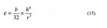
In fact, with mirrors so small and light, involuntary pressures of hands lead to displacements of the workpieces and unpleasant surprises. Instead the work by sitting in front of the glass, where the tool is turning slowly on a vertical axis, It makes things a lot easier. The pedal lathe for Optical the following figure 84, It is considered to be the best machine for small works of precision optics (2).
Placing such a lathe you will choose the slowest speed and the actuation of the pedals slower and constant as possible at least during the precision polishing.
However, you can improvise a lathe for a casual work, directly using the slow axis of a screw moto-reducer worm, on condition that its rotation does not exceed 15 rounds / me (see below 85).
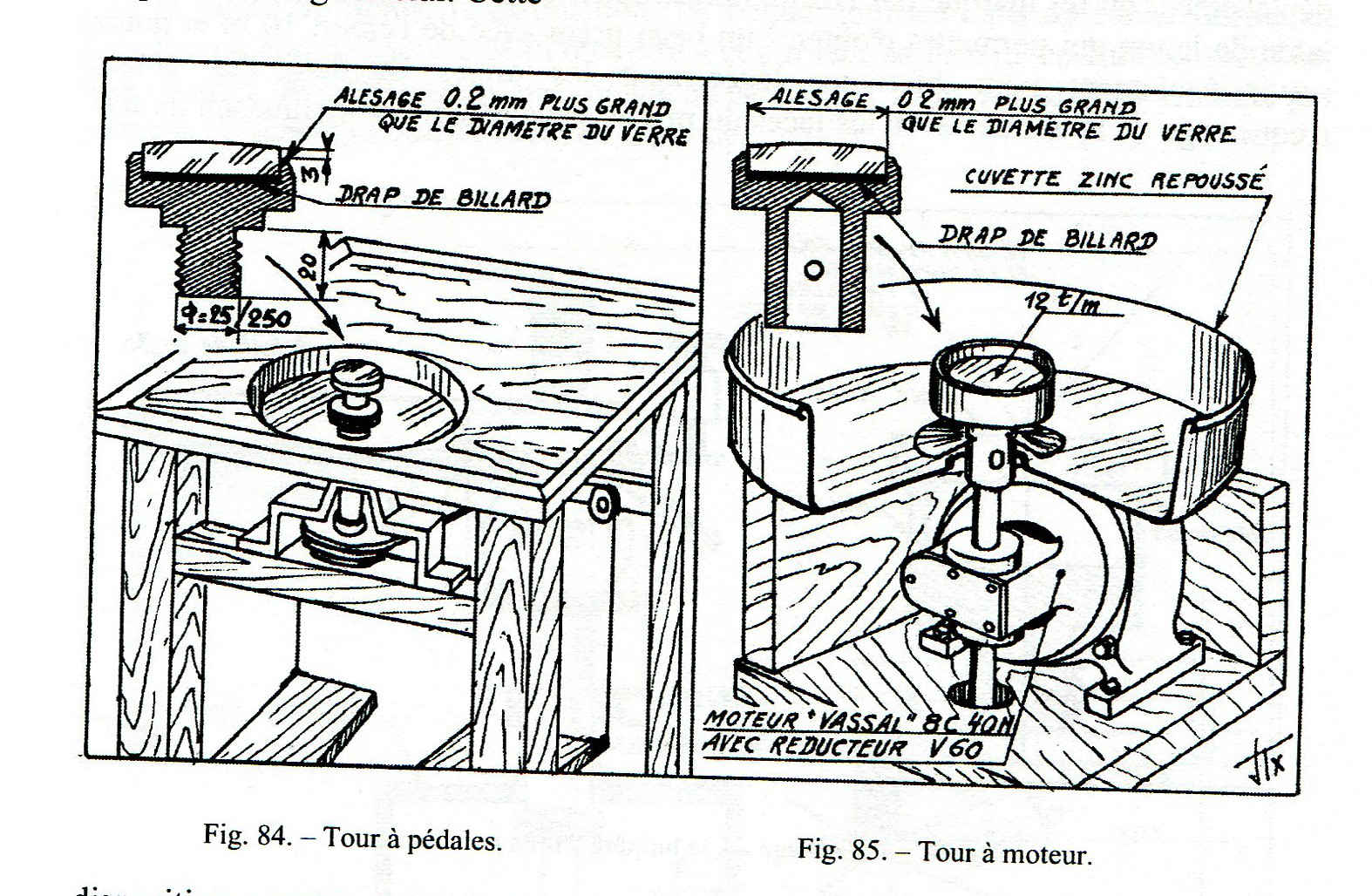
Figure 84 – 85
(2) Manufacturer Clavè, 9, rue Olivier Metra, Paris 20 °
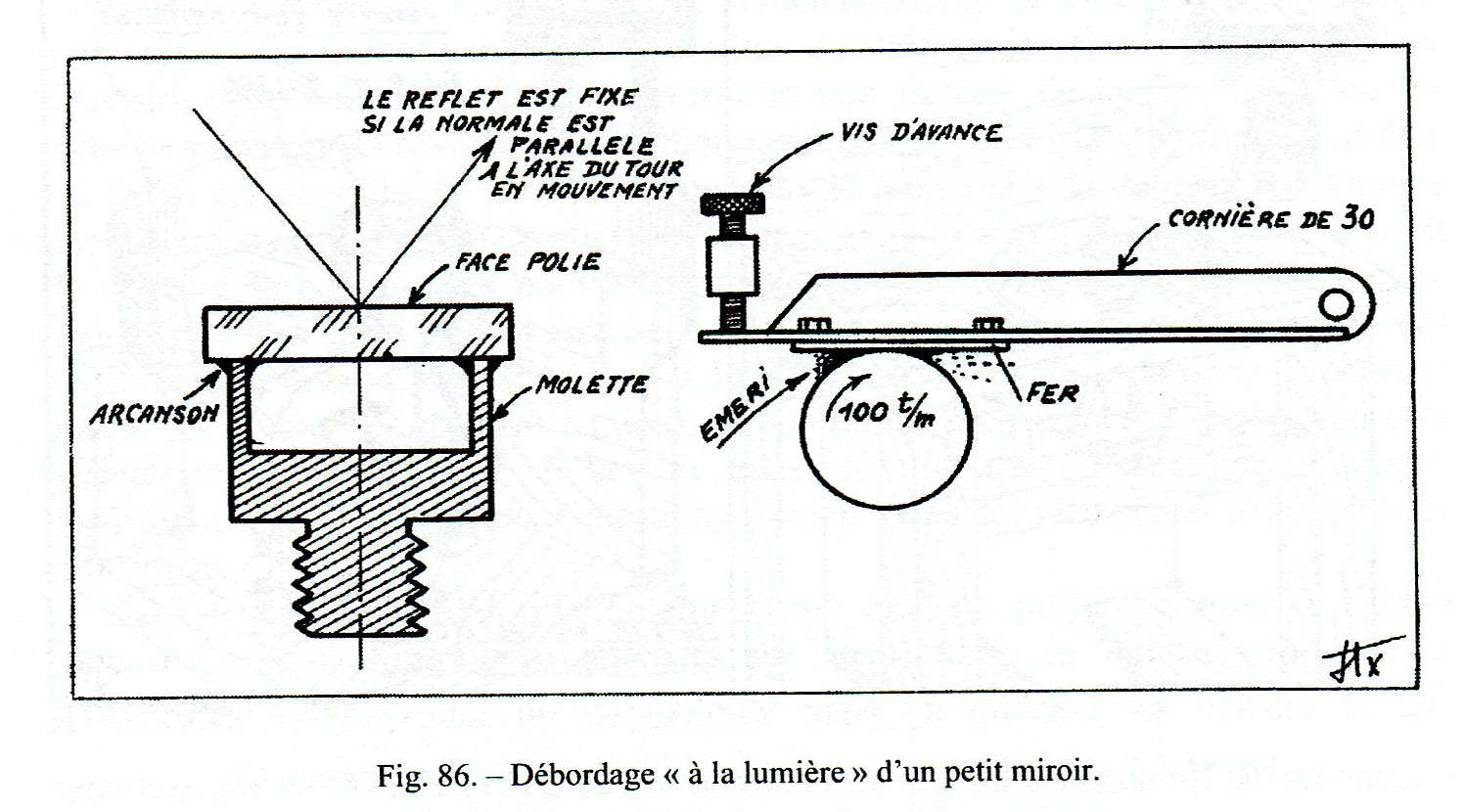
One of those industrial lathes and polishers includes a tool to hold pieces with a standard threaded shank diameter usually as have several wood turning tools. The glass to be machined are fixed thereto for pitch based means of glues or rosin as one called "cement for optical", or what the French call "Arcanson"(1).
We prefer to mount the glasses to work without constraints through special adapters to bowl receiving the lenses on a cloth disc loosely.
This fixation (shown in Figure 85) It allows to control or reverse the processing in glasses without having to detach and re-paste at each reversal position. There are bowls of adjustment light alloy or simply hardwood, that can be mounted directly on a rotary axis of the lathe, or simply be stuck on a rotating plan submitted by an eventual existing tool of the machine (see figure 86).
79 Processing for refining the raw edge.
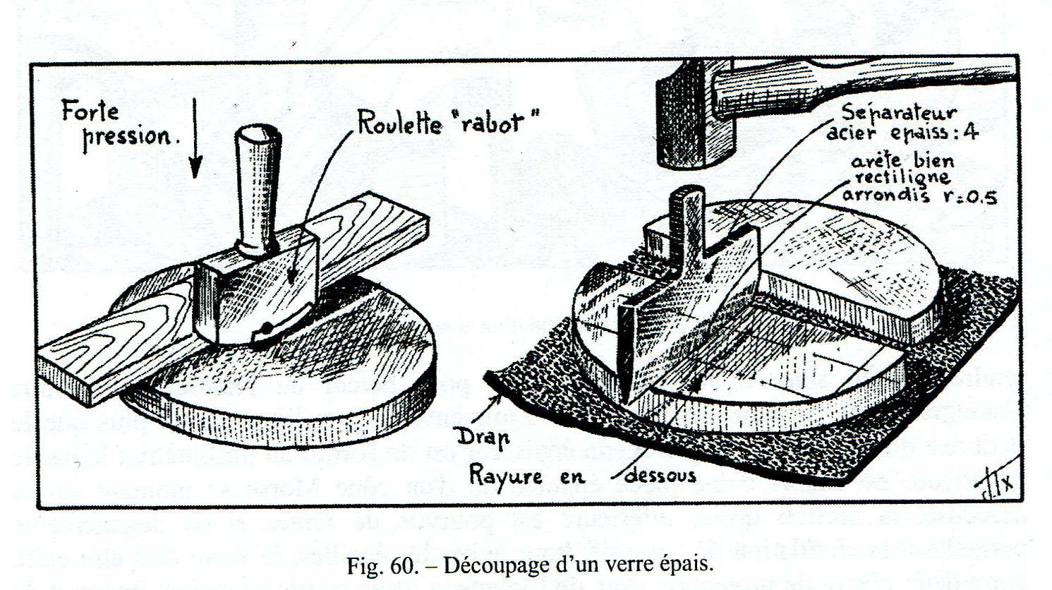
To accomplish mirror and tool it can be used as one raw material processing waste in normal glass from Saint-Gobain 10 until 15 mm thick.
After the summary with the classic cut glass cutter to press wheel or diamond (fig 60), or with the tool made with a simple iron pipe in shape of Cup that cuts in wet with interposition of Emery grain (Fig. 61) the glass is glued to the Rosin on the wheel to support the piece of the lathe (fig. 86). Before the rosin cool completely, you have to correct the position of the glass so that the faces which are polished are turning well centered on the media, to ensure both that a rotation centered perpendicular to the axis of the machine.
A classic way to test this centering and squareness is satisfied, is to make sure to see the immobility of a reflection image of a lamp or window, coming from the upper surface of the rotating glass.
This centering said “at the light” is made with great care for a lens that should be centered since from its construction, destined for example to be inserted into an optical system that provides strong convergence, but here in this case the secondary mirror, a shallower control is amply sufficient.
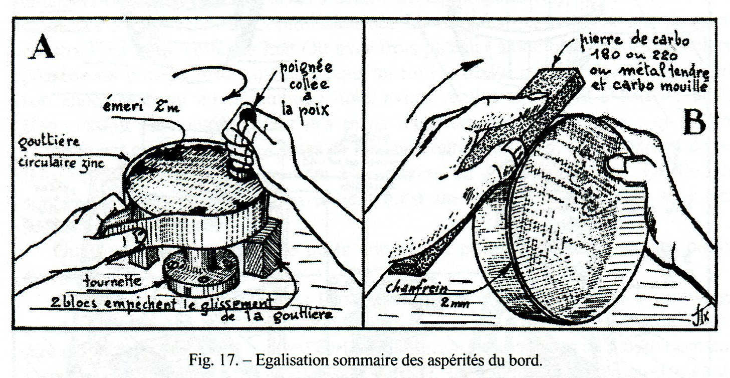
You have to wait for the complete cooling of the Rosin before beginning the break-in / aging / regularization of the edge of the glass. If the latter is irregular it starts with a brief equalization with a zinc-end (see Fig following. 17 A), using an emery grit 1 minute, actuating the lathe at a speed of approximately 100 rounds / me.
(1) For details on these classic works, refer to the glass optical Worker support precision, written by Colonel MUST (Ed. optical Review).
But to make the glass exactly cylindrical is good an iron articulate on a fixed point, and pushed by a feed screw (see below 86). You use the emery of grit 1 minute or 2 minutes as long as the noise abrasion remains uneven , to indicate that it is still uneven surface to even out the mere contact of iron coated with wet Emery , without pressure.
The change of Emery grain will be accompanied by a shift of the moving iron corroded from tangential consumption, or it will be replaced with a brass knife that will provide a fine-grained emery with 10m and may well serve to lightly smooth the edges that are increasingly fragile.
Defects squaring the edge of the mirror are corrected by tilting the iron.
80 roughing.
Glass on glass processing provides two interesting pieces that are both polished by applying control with the method of interference referred to in(chapter § 77)
(N.D.T. See equivalent articles about interferometric Newton's testing in this blog:
https://www.grattavetro.it/interferometro-di-newton/ ehttps://www.grattavetro.it/frange-di-newton-concavita-e-convessita-delle-superfici-in-esame/ ). .
The convex glass will be the mirror, whose flat back, to be polished, will be protected with shellac varnish against possible damage resulting from working the front face. The concave tool will then be polished to become concave caliber, and it is advantageous that it is carried about the 10% largest mirror, something that doesn't irritate the abrasion and will disregard any error TDE of inappropriate turned down edge.
The rough grinding occurs as at the fixed table, the glass we make convex is placed bottom, IE supported by lathe holder of piece.
Given the small amount of glass to remove, the emery 1 m or 2 m and strokes of 4/5 d but poorly decentralized , They are sufficient to rapidly achieve the desired curvature.
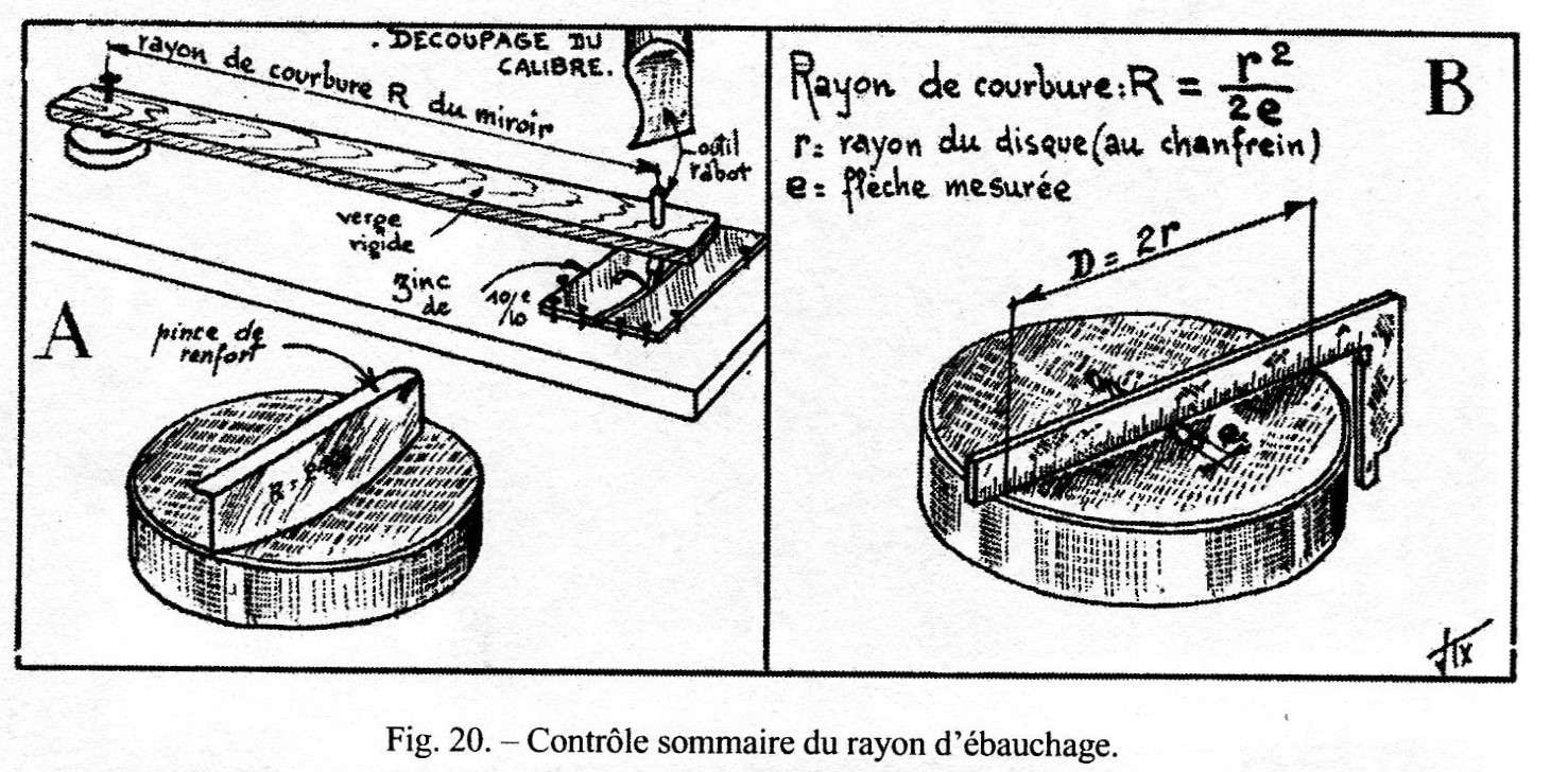
For the verification of the radius of curvature reached at this stage, is simply to use a mask or template made by cardboardor or zinc, cut directly at the r2 calculated RADIUS of curvature.
Meet that are the desired curvature you must regularize by applying the usual strokes with amplitude 1/3 D . With the same stroles we regularize the surface in reversing the position of the glasses that require two different adjustments on both sides.
After the usual meticulous cleaning and precautions that prevent unwanted scratches, You can switch to emery grain 5 and 10 m but making a little shorter strokes than 1/3D due to the fact that the cocave tool , that is greater than our mirror,, has the negative trend to turn down its edge.
The reversal of the position mirror – tool should be used not only to correct a curvature RADIUS too long or too short, but also systematically to every wet to keep exactly the same radii complement of two glasses.
The precision of the control possible with a simple model of the curve in cardboard or sheet of zinc (Fig. 20 A, page. 33) is unsatisfactory for accurate verification of a secondary radius Cassegrain. The resulting focal length and the conjugate points are very sensitive to this parameter.
therefore, to measure with due precision the deep of the arrow, It can be used a cup spherometer as shown in Figure 87.
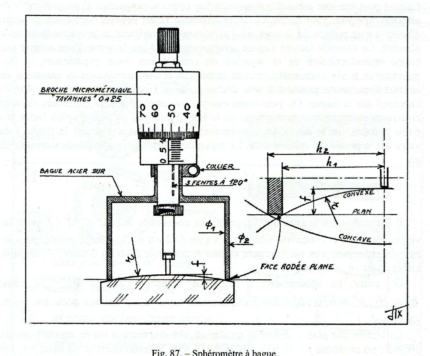
The cup turned hard steel, It has a diameter a little less than that of the glass to be tested; its annular contact surface is ground after hardening and / or tempering and over lapping with grinding grit 5 e 10 m, for example on a cast iron floor, and the edge that defines the circumference of the contact surface of the cup must be well vivo.
81 Spherometer cup (or ring) see previous figure 87.
As you can see right into fig.87, a head micrometric measurement allows to measure this constant with an accuracy in the case of convex glasses, Ø1 / 2 = h1 and concave glasses Ø2 / 2 = h2.
The Cup has a 120° axial slots to ensure elasticity and centering to a metal collar type clamp fastener that joins a micrometric measures head type Palmer.
This measuring device fits very easily to a variety of structures, for example, the thicknesses of controls or parallelism of quartz plates for birefringent filters, or for closing slabs of telescopes, or for Schmidt blades, the objective lens, etc …, We would not hesitate to recommend the best screw possible. For example, a step 1 mm, it is preferable to 0.5mm, the chrome drum must be of large diameter in order to allow an easy interpolation of readings per micron between notch and notch.
In the case that there is concern of incurring a constant error in measuring a concave glass of small radius, the tip of the probe of the measuring head micrometric (ie the tip of the rod-contact measurement), It must be reduced to a maximum of 2mm diameter, polished or even as a small area of the convex surface. Whereas it would be useless the mechanical complication of a non-rotating head of a measurement screw. The implementation of the measure should enable an extremely smooth rotation of the screw.
Despite whatever they may say treaties mechanical measurement, If you avoid using the Torque limiter of the micrometer (which it is usually always set too hard) You can define a contact with a fidelity of a micron, with the simple mastery of hardness to maneuver of the drum delicately manipulated.
A first reading serves to annotate the measure corresponding to the zeroing from screw contact and edge of the Cup, and it does so with the spherometer laid on a reference flat. The flat may be an optical piece sacrificed for this purpose, but it is better to prepare once for all a finely ground glass surface and polished only for fifteen minutes with a pitch tool, to use for Interferential verify of flatness .
The second reading is made by transferring the spherometer on the glass to be measured.
(N.D.T: With the zeroing of the spherometer, the edge of the cup finds himself on the same level as the Central probe tip; but when the instrument is placed on the convex glass it will touch initially only on the tracer point that will be set back by rotating the micrometer until the edge of the Cup reaches the contact with the glass).
In order to ensure good reproducibility of the contact pressure of the two measurement experiments, You must maneuver the micrometer screw very slowly and record the feeling of frank contact made, corresponding to a discharge of 1/3 or half the weight of the tool on the rim of the cup.
You can then also try the different increasing microns, by appreciating the weight discharges of the sferometer, making it increasingly easy to turn the screw on the glossy surface.
The subtraction of the two readings provides us with the arrow f within the field of application of the spherometer.
The corresponding radius of curvature r It is calculated using the following (19):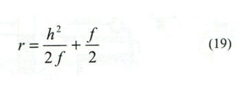
It is practical to register on the device the constants h12/2 e h22/2 for convex and concave glasses. Since the term f / 2 is often negligible for astronomical mirrors in which F It is small compared to r, one only Division will provide r as in the following example where all measurements are in mm:
Uses a cup spherometer with inside diameter of the ring Ø = 52 mm, so h1= 26; h12 =676; h12/2/ = 338 is the constant to consider for convex glass.
The reading on the flat gave the figure 10,334;
the reading on convex mirror 10,993.
It we deduce f = 10,993-10,334 = 0,659
the beam is then searched = 338 / 0,659 = 513.
If we want to avoid any harmful approximation calculation, We drive the division to a decimal place, here we will write 512,9 and add f / 2, namely 0.3 which it gives a more accurate within 513,2. But we must never forget the physical meaning of the limited sensitivity of a micron, which represents here an approximation of ± 0,8 mm on the radius (1).
82 aging.
Since the beginning of the refinement of the surface it is necessary to respect the final curvature RADIUS with the best approximation possible. This allows you to often reverse position tool and mirror, and it leads to more easily obtain surfaces perfectly united, ie identical but complementary, namely having exactly the same radius of curvature.
- spherometer bending of A. Couder allows only approximate to the tenth of a micron, while the comparator dial instruments are generally loyal to the best of several microns, except when the support brackets are very harsh.
For such small mirrors, 2 or 3 wets of each emery 20 m and then 40 are enough to conform the surfaces. The final inspection of the radius of curvature must concentrate on the mirror and on the tool. We must make sure that the arrows are situated exactly concordant (of course taking into account the different constants of spherometer). Indeed, with fine abrasive polishing grain would already be very difficult to realize a correction of only 2 m, ie approximately 7 fringe. A meeting of perfect uniformity between the two disks can be achieved with a finer emery: 60 m o “304” conducting partially the last half polishing wets with the tool above and half by reversing with mirror above.
83 polishing and retouching.
The two tools can be derived for example from two wooden discs thick plywood 15 mm on a face turned exactly to the radius of curvature (occurred with good accuracy with the cardboard or zinc mask-pattern) and also turned to the diameter of the corresponding glasses to allow the immediate reversal of the glass position - tool
The two wooden disks must be waterproofed (in years it is gone by full immersion in paraffin, Today there are polyurethane coatings).
It begins with a sleeve covering the tool with a curved casting of pitch without blockiness.
To make the casting must have a tape containment band of paper 50mm high on the perimeter of the wooden discs creating a container in which to pour the molten pitch up to a thickness of approximately 6mm.
As soon as the cooling is sufficient you can remove the tape containing adhesive.
It then proceeds to a pressing of the pitch on the glass curve initially with a strong pressure with an interposed sheet of paper-silk / sheet of kitchen polyethylene.
Finally takes off the paper or polyethylene, and you run a pressure of better adaptation with pitch previously brushstroke creamy abrasive (usually of cerium oxide and water).
You can therefore practice a diametrical groove, or a cross-hatching of grooves digging, (image 88 A) or a spiral a little recessed realized with a very sharp scraper. These depressions on the pitch must be maintained or redone regularly throughout the processing to improve adherence.
(N.D.T. The grooves or depressions must imperatively be always present in the processing of optical mirrors, and serve to prevent zonal errors due to uneven wear of the pitch, that could inflate at certain points, or vice versa lose contact other).
Since the main concern is whether the windows are sufficiently close bending radii, it starts with the polishing summarily but uniformly over the entire surface, before the tool caliber and then the mirror for ¼ hour each, and then proceed to a first summary interferential control.
If it indicates a significant difference in the curvature of greater than 8 or 10 fringe, it is better to resume polishing to obtain a unification of glasses with greater accuracy.
A difference of concave curvature - with glasses that are touching the edge – it is more difficult to recover a relative convexity; Is’ Also desirable to start with a convexity 3 or 4 fringe, It leads to an easier polishing.
Since the curvature corrections much easier the more the glass is not completely lucid, It is better not to work soon for the caliber, but push the mirror polishing to about 75%, approaching then the curvature of the caliber by means of the simple choice of position under or on top of mirror-tool.
If you need to increase the convexity, the well-understood convex mirror must be under; and vice versa to increase the concavity of the concave. However, we must work so that the gray (understood as yet matte surface) It is not too unequally distributed between the center and the edge.
The polishing of the caliber takes place with the arrangement (up or down) convenient to reduce residual curvature differences with respect to the mirror; Could be useful for this purpose of longer strokes than normal (from 2/3 until 3/4 D) it will help if necessary correction, but care should be taken to deformation! Of course it is completely unnecessary to polish the caliber; as soon as the glasses don't have to one or two rings that you will proceed to the keep in spherical shape of the caliber, that the approximation we are interested (0,1 fringe). But this is not a transaction as easy as it can believe those who have no experience.
The gauge control is made easy with the Foucault method (in the manner described in § 29 e fig. 33, of page. 55 and the following).

Figure 33
If necessary, the tester will be slightly amended by turning towards the knife out of the light source and installing a small 90° total reflection Prism that will bring up a few millimeters the light beam of the slit to the optical axis at the knife edge (This means to reduce to a minimum possible the distance from otical axis and light beam of the source slit – knife shown in enormous 25 or 30mm in the following constructive design of the Foucault tester in Figure 34).
If you want to contain ignorable amount of the extra-axial aberrations assembly, necessary to reduce the distance between source, knife axis and the optical axis, less than 10mm for a mirror of about 500mm radius,
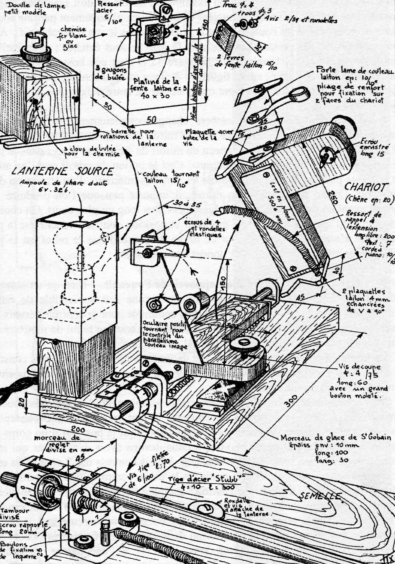
Figure 34
Similarly, the primary mirror, you must try to immediately get the best possible shape. Is’ well welcome to fulfill some repetition, given the importance of this result. Working preferably in a room where the temperature is from 20 until 24 ° C.
Use a tool with good pure pitch , quite a little hard for a small glass (the nail of the thumb should slightly mark the pitch under a strong pressure), but mostly use pitch that is NOT dried from an abrupt heating, because he would lose the flexibility granted by volatile solvents lost.
Working with strokes 1/3 D for small wets pushed though long over time. Use a low rotation speed of the lathe, Is’ the back and forth movement practiced hand that must be winning.
Later, after 3 or 4 wets the pitch must have a surface evenly covered with abrasive (for example cerium oxide), and issue its characteristic smell of conifer much more than it emits cold.
It must be ensured to avoid clogged channels of pitch (see previous figure 88 A) in such a way that the tool maintains good adherence.
The work is set by the amount of abrasive (iron oxide rouge, or white zircone or Cerium oxides) with water, just as important is the percentage of the two components that will put in each wet. It must be a serious and effective experience to take impeccable wets and a good tool.
Beginners often put too abrasive or too much water at a time; In the course of work, should be sufficient to complete a wet only one brush stroke of abrasive on glass.
Believing that you apply these tips to the letter, many are surprised by zonal defects that appear irreconcilable, and that are generated regularly, whose fault may be an insufficient thermal regime (given by pitch too hard, or wets too short, or insufficient works time) that often results in a surface with turned down edge and center high (see previous figure 33 D).
Center high correcstion is not difficult, and you do so with mirror under and tool over and strokes centered. As regards the Turned Down Egde, of which we do not recommend the retouching on a small glass, You'll also want to overlook it, if the exceeding of the gauge diameter will suffice, If not you should try again improving your technique.
Once the Foucault test shows that the caliber is well rounded in the useful portion (see previous figure 33 - ), We just have to complete the representation of the convex mirror. The interference fringes observed between spherical caliber and the actual mirror, generally reveal a set of difference in curvature and deformation sometimes used directly to start the Hyperbola. But the most secure normal method is to immediately correct curvature to bring the spherical mirror to obtain the rectilinear fringes of the previous figure 82 D.
It only remains to realize the hyperboloid, which it is slight in comparison to the previous job.
When the deformation does not exceed 0, l 0,2 fringes may be carried out a sufficient retouching with his thumb or forefinger (§ 43). But generally it's best degarnish away the normal tool in form of circular crown of medium radius 0,7 (fig 88B); used after with strokes a little short from .25 to 1/3D.
In addition to checking the maximum height difference e about the zone 0,7 (previous figure 82D), You must verify that the curvature present the desired trend .
Those who are not very familiar with this deformation can cut into a paper mask the Central curvature for a given inter-fringe calculated by the following equation:

Image 88 It provides some examples of hyperboloid and their retouching.
In figure 88 C beaded edge is insufficient, a local tool used on the areas to depress you'll complete the action of the crown tool . Sometimes it is the central role that does not come with the exact profile (fig 88 D), you can groped a local retouching, but it is often desirable to resume the puttin in shape after a return towards the sphere.
some operators, whatever they do, fail to prevent the Turned down edge. When this fault is not entirely hidden by the frame of the telescope, It remains them the possibility to realize the secondary mirror with an oversized diameter (Look images 88 Is) and then use it only on the useful diameter masking or removing the hatched area in fig.88 E.
***