One of the aspects that usually remain unclear, during the design phase of a mirror roughing is what must “to dig” to reach the focal length of the project, before moving on to the next abrasive granulometry.
Who has a fair number of self-built mirrors, now possesses the experience is the ability to assess whether it is digging too much or too little with a certain grain of abrasive, who is instead struggling with the first mirror usually makes a random choice, thinking : ” dig a certain percentage X of the final depth with the abrasive Y and then try to dig the rest with other abrasives while regularized form”.
In these cases, It is comforting the thought that we can always correct any errors with the inversion technique of position between mirror and tool, that will allow us to “come back” at any time to increase the radius of curvature of the mirror if we realize that we have dug too.
However, I believe that no one has really used this technique, if not for the maintenance of (alleged) shape. I think instead, most of us, We have found at least once in the position of not being able to reach the last “ten centimeters” and focal length with the abrasive 1000, or with “infamous” stroke 1/3 COC (1) (2) (3) which, the only thing that really succeeds in deepening, is our performance anxiety when we realize that we will never achieve the desired focal.
Unlikely, however, the question of the focal construction is designed and programmed, as for all other design parameters, before starting processing.
Let us then describe a method to plan and assess correctly the construction of the radius of curvature and thus the focal length, chosen in the design phase for our mirror. To do this some preconditions must:
Dispelling A MYTH
Past to 1/3 COC does not increment the depth ( but to no )
Anyone who has tried to increase the depth by using the past to 1/3 COC has noticed that this method does not work , or at least the 'increase the depth to each dried is so small as to be irrelevant, see why:
When two glass discs are perfectly superimposed on one another with the interposition of abrasive, the pressure is evenly distributed across the surface. Under these conditions the abrasive action on the glass during the rubbing is the minimum possible.
If you move the top disk by placing its center ( which it is also the center of gravity ) on the edge of the lower disc, we will have that in this position you will have the maximum stress between the two surfaces and it is precisely the point where the abrasive action will be more effective and the greater glass consumption.
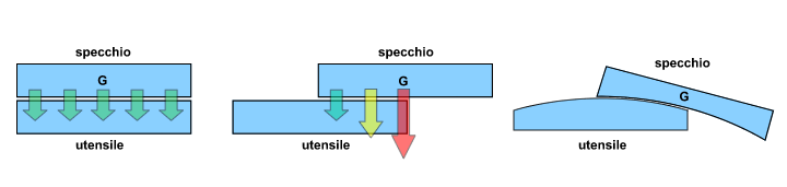
Fig.1 – pressure distribution
This is also the reason why the upper glass becomes concave and the lower convex and is also the assumption on which is based the stroke “Cordale” which famously, It is one that allows to dig the maximum possible with the minimum of work.
we can say that:
the glass consumption during the rubbing is minimal when the two layers are superimposed and increases at the center of the upper disk, as much as you move toward the edge of the lower disc.
Keep in mind that we are talking about two discs of the same material, in this case the glass, things are a bit’ different when we use a tool with a pitch patina on the glass.
This makes us understand why the past 1/3 COC is ineffective as an increase of the depth at the center and to be effective for the regularization of the form as:
- The distance between the two centers will be at most 1/6 the diameter.
- The two glasses during the races to 1/3 , They will always be in a position to distribute the pressure over a large part of the distributing surface almost uniformly throughout the abrasive.
So forget to create depth ( except at very small “doses” ) with the most classic of the past and we reserve the right to use her, namely regularization of spherical shape.
DEEPENING STROKE’
Now we need to find a past that combines the features of chordal and 1/3 COC namely, which allows to generate depth at the center quickly maintaining a spherical shape as much as possible. We can not afford during the finishing touches to the focal with a fine abrasive, to ruin a form already regularized to add a few cents mm deep.
With the additional premise that, we refer to a purely manual processing, you have to race our case is depicted in this scheme and we will call “deepenig stroke”:
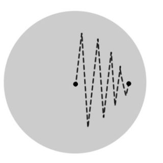
Fig, 2 – depth Stroke
Is’ very similar to the classic Points “W“ Extended half track, It differs from this due to the lower intensity with overlapping centers , In fact, this being a point of “end / start race” It will have a softer action with respect to the full step. It is then to move the upper glass forward and backward from the center of the center, extension until 2/3 D and pressure applied to the center, They move simultaneously towards the edge and decreasing the amplitude of the races, not to exceed with the ooze in the peripheral part.
- mirror above: In this mode, it generates an increase of the depth at the center and consequently decreases the radius of curvature ( focus )
- mirror under: It reduces the depth to the center of the mirror with a consequent increase in the radius of curvature.
ROUGHING PLANNING AND GRINDING IN FUNCTION OF FOCAL
Let us now try to quantify the effect of this technique on the removal of material.
The following table is the result of measurements made during the processing of a secondary from 125 mm, whose focal F3.12 ( radius of curvature 776 mm) It was built during roughing, by applying these simple pass after running the first large study with past chordal. The results have been extended to a possible mirror 300 mm F5, but not in this case the result of direct measurements.
|
GRANA ABRASIVO |
DEPTH x annoyed (mm) | FOCAL CHANGES (125 F3.2 ) | FOCAL CHANGES (300 F5 ) |
|
80 |
0.04 | 8 mm |
1.6 cm |
|
120 |
0.02 | 4 mm |
8 mm |
|
220 |
0.01 | 2 mm |
4 mm |
|
320/400 |
0.005 | 1 mm |
2 mm |
|
500/600 |
0.0025 (*) | 0.5 mm (*) |
1 mm (*) |
| 800/1000 | 0.001 (*) | 0.02 mm (*) |
0.4 mm (*) |
(*) valued
n:b.: the relationships expressed are indicative and contain approximations for ease of reading , the actual values of the ROC as a function of the increase of the depth, They are obtainable by simple mathematical formulas.
The following example, the succession of abrasives for the generation of the depth for the mirror 125 ( 123 actual ) It was well planned, and performed the necessary sessions until it reaches the desired depth:
|
GRANA ABRASIVO |
TECHNIQUE | DEPTH’ mm |
R.O.C./FOCALE mm |
|
80 |
Cordale | 2.0 |
940/470 |
|
80 |
1/3 COC (regularization) | 2.0 |
940/470 |
|
120 |
deepening stroke. | 2.25 |
840/420 |
|
220 |
deepening stroke. | 2.36 |
800/400 |
|
400 |
deepening stroke. | 2.42 |
780/390 |
|
600 |
deepening stroke. – 1/3 COC | 2.44 |
776/388 |
|
800 |
1/3 COC | 2.44 |
776/388 |
The figures do not provide a general rule, much depends on the personal processing operator , the type of pressure applied, from the speed of execution, etc… which could lead to more or less different results, but anyway, applying this technique from the start, even without using the chordal, you can measure the variation of the obtained depth and raffrontarla with the table, up to build their own table “effectiveness of the excavation” that will allow us, for successive mirrors, of advance planning the succession of abrasive, with the great advantage to always stay next to the spherical shape.
One could argue that, in this way, It is not the classic criteria for the evaluation of the change of abrasive, in which it is determined to move to the next grain, when i will be gone “craters” generated by the previous grain, and the surface is uniformly polished.
Is’ a calculated risk, one might find in fact in a position to reach the desired depth before they have standardized the abrasive surface in use. In this case, just stop with the depth and continuale racing with classic racing 1/3 COC with alternating mirror position / tool, that stabilize the depth reached while refines the surface.
Cami
Giulio TiberinI