With reference to the previous article that dealt with the construction of this instrument; So as not to lose the habit to DIY, but above all in order to get rid of the stool needed to reach the eyepiece of the telescope that was in 1,8 meters above the ground. I lowered the same 16 cm, bringing it to a lot more comfortable height of 1,64m.
A direct me on this road was the article published on Sky and Telescope February 2013 of page 63-64, on new philosophies “do-it-yourself”, suggested by Albert Highe, and developed in his new book published by Willman Bell, by title: “Engineering, design and construction of portable newtonian telescopes”.
I then built a new secondary port for the diagonal of 63mm (After careful design cad) not already tilting of 45 ° relative to the horizontal, as is the norm in all telescopes newton, but only 33 °. Which led to the orientation of the eyepiece that was horizontally, at an angle of 24.52 ° upwards.
In total, the telescope balance is much improved, not only for the most reduced overall length of the Dobsonian and consequent physical lever arm, but also for 300 grams of least shorter than the trellis weight of (8 x pieces 15 cm each)= 120cm of Ø22 aluminum tube×1.5 mm.
In fact the reduction of 300 grams in weight at the top of a telescope with a focal F6, match (300 * F)= ~ 1800 grams of deleted balancing weight to the primary case.
The part most “difficult” But the whole thing, He was to figure out how to retrieve the secondary mirror GSO “naked”, pulling it free from inside its plastic support supplied as standard. I then drilled three holes “exploratory 8mm in the original plastic support, and then, illuminating the interior through one of them, and looking through the other two, I noticed that the edge of the mirror showed three tiny projections of double-sided tape in conjunction with the contact surface with the support.
UnVeiled of its fixing mode, I then pushed gently on those projections, entering into the holes with a screwdriver completely nylon (for the tuning of the high frequency equipment), ….and the mirror has meekly surrendered breaking away without injury.
In constructive downsizing I wanted to reuse the secondary as well as 63mm and 31.8mm from the focuser.
This reuse, coupled with the shortening of the truss, It resulted in slight limitation of the previously set full light field, because the light passing diskette per barrel from 31.8 mm has a maximum useful diameter of about 28mm, which, however, he would go "out" with a diameter of 63mm secondary. In other words the secondary would have "vignetted" the reflection of the primary diaframming it by fact.
The limitation that I adopted to prevent the vignetting was wearing a 0.3 degrees for part (0,3° 0.3°), For a total weight of 0.6 degrees, the wideness of the angle of the sky observable. The diameter of the light spot from 0.6 ° to the focal distance of 1812.6mm, they provided me with a "Field of full light" amounted to:
2*[TAN(0.3°)*F(1812.6mm)] = 18.98 mm.
The construction of the secondary mirror tilted by an amount different from the usual 45 degrees, does not involve mechanical problems, nor opticals, HE we respects the law “Descartes – Snell, or" law of Sines ", for which the angle of incidence and the emergent angle of reflection are equal, and then according to their identical opening must be aligned with the optical parts. Thus, even the stars at the edges of the field of view from the telescope appears as pinpoint and unchanged compared to previous telescopic vision with the secondary at 45°.
The new tilted support for the secondary was constructed by combining simple corners aluminum, so that the new angle of axis deviation of observation result equal to 65.5 °, determinasse an angle of incidence of 57.26 ° of the beam coming from the primary, and identical amplitude angle described by the emerging beam, that is reflected in output from the secondary to the focuser, as you can be seen from the following drawing (magnificable if you click on it).
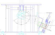
(To the Focuser are as well indicated the extraction distances of the focus, measured on each of my eyepieces Park)
in phase of collimation, the alignment of the optics with its tilt movements of the secondary mirror, guarantees, nothing more and nothing less, than what happens in telescopes with 45 ° secondary , that the optimal angle of incidence, is precisely found every time automatically, in achieving optimal collimation .
The secondary mirror seen from inside the focuser, It is no longer circular but elliptical, with axis (measured on the CAD projection) of 63 x 80 mm, that is leading the obstruction from the original value of (63/305)*100 = 20.6% of the normal configuration, to the value of (71/305)*100 = 23.2% in the current configuration.
Where the diameter indicated with 71 mm in the last formula, It is in fact the diameter of a circle of area equivalent to the one presented by the ellipse 63 x 80 mm, which it is the real obstruction given by the new inclination of the secondary present in the optical path in the new configuration.
CONCLUSIONS:
The result (at the moment…) is a telescope 305F6 low and easy, that no longer needs a stool for me to see objects at the zenith, and it has a light structure (27 kg) but stiff, and requiring only a small collimation refining at each Assembly “on the field”.
Also here, a few photo gallery is definitely the best technical testimony “multi-Language”, comparing a thousand words.


