- This topic has 56 replies, 7 voices, and was last updated 6 years, 9 months ago by
Giulio TiberinI .
-
AuthorPosts
-
18 July 2017 at 15:10 #10126
Ok, I saw and I realized that he had put the diameter of the mirror instead of the radius
 26 July 2017 at 21:08 #10181
Hello again to all!

I finally managed to finish some finite element calculations with respect to the blank, I came to the conclusion that a 10mm thick 400mm blank supported by “drawing” rear 20mm thick is structurally very good…you as you see it? That is knowing that I have to dig a little more than 5mm arrow on the slab where the solid part is 10mm thick, do you think it is too “dangerous”?26 July 2017 at 22:11 #10185I personally find it very difficult to assess the risk of instability still quite high, why “a naso”, I would say that the mirror being the result of a fusion with a non-simple structure, there will invariably of internal residual stresses (perhaps even visible in polarized light) that should be eliminated with some form of distenione the result maybe not perfect, otherwise the poor response of the stability after the excavation of the arrow. To avoid risks precaution I aumenterei the initial thickness 15 20mm or so that after the excavation remains a greater thickness, or confiderei in détente and accept the challenge, hoping that no fiventi jinx.
But I think Mirco or Maximum can be more reliable than me.
27 July 2017 at 6:48 #10188Here, in respect of residual stresses, There are 2 roads: the first is trying to follow the blank a certain temperature curve during the cooling; But the process takes about 40 hour…
The second consists in carrying out the melting and allow to cool normally, subsequently carry out an anneal, the process is much faster (I'm 30 minutes at T annealing followed by a cooling of about 30-50gradi / hour up to ambient T) e, to what I was told, should eliminate any type of voltage27 July 2017 at 9:51 #10189To check for contractions in a blank, there is the de cryptographic method in this very interesting article:
http://strock.pi.r2.3.14159.free.fr/Ast/Art/Tension.htmlBut it is possible to see the presence of important internal tensions, now wearing sunglasses with polarized lenses.
Indeed, if you've never noticed, try to wear glasses with polarized lenses (like the best Sunglasses, or transparent ones that are worn to see the movie 3 dimensions), and then watch a tempered glass as any car window except the windshield (Today that is no longer tempered)…and you will clear the dark plot, or iridescent depending on the incidence of light, of the grating-shaped contractions, holding the glass together for compression.27 July 2017 at 18:11 #10191interesting article! Ok I think I will keep the full part to 15mm, after the merger will check if there are voltages and based on the result do see if annealing or less…The last problem to solve is then to find the oven
 27 July 2017 at 20:17 #10192
I think yours is the right choice
 30 July 2017 at 12:44 #10204
Good morning!
soon I will begin with the creation of the mold and wanted to be sure of one thing…
of guiplop must enter the measurements of the secondary mirror for precise measurements of the diameters on which lie the support pivot. I checked, and in the end it turned out that the minor axis should be about 90mm (slightly oversized). What I wonder is if the height of the focuser is more or less standard, or if there is some way to size the mirror which is fine for most of them30 July 2017 at 15:18 #10205The height of focusers for reflecting telescopes nowadays does not vary much more than in the various manufacturing brands, It is now in all “low profile”, ie very compact, whether they are of the type “rack and pinion” that helical. The compactness is delegated by the need to contain the distance of the center of the field full light sabilito for ocular (or for the CCD camera), from the optical axis of the primary mirror, and with it determine the useful diameter of the secondary mirror, and the diameter of the case that will hold the secondary.
All this in order to minimize the obstruction of the telescope, which penalizes the contrast of images, due to the diffraction of light displacement from the notch to the first rings of it. Increase of light in the diffraction rings that notoriously notch decreases the puntiformità stall and then the contrast of the strrumento..
In general, the distance from the base of focusers fixing to the point where it would be in the field diaphragms of the eyepieces is about 10 o 15mm, who goes agiunta their race focheggiatura which is normally included in 35mm, sempree for the reason stated above.
Is’ But other than the normal way of approach to sizing the secondary mirror. and all the mentioned parameters that are connected to it.
On-line there are many small programs which calculate the size of the secondary unbeknownst to the user, which introduces the data to read an outcome that must accept uncritically.
Usually instead, the correct dimensioning design of a telescope which has been defined as the diameter and the focal ratio of the primary mirror, He goes on to calculate the full desired field light for the instrument, the magnitude of which will depend on the diameter of the eye that will be used, or the amplitude of the field of the CCD camera; The amplitude which must then be plotted on a scale drawing, from which they will make all measurable constructive dimesioni above, taking into account that if it abounds in any size, It is unfortunately also abounds in penalization given by obstruction…and to promote the contrast (a l”High Definition”..as we say today) it is always better that abound in deficit.
./. Follow
30 July 2017 at 22:34 #10214Followed by the previous post:
Now I do to look good (because a secondary 90mm seems very oversized)
 :
:The calculation of the size of a secondary part from the calculation of the full desired light field (from which also derive ALL the constructional size of a telescope which has already chosen the diameter of the lens and the focal length) and it is in the following reasoning, I try to do helping attaching two enlarged views of the important parts and the corresponding set in a special little drawing CAD.
A point star placed indefinitely on the axis of a telescope 400F5, form with a mirror given a cone of light that has as its base the primary edge and vertex as the fire at the distance F5 (ie 400×5=) 2000mm (the cone lines in green in the little drawing following)
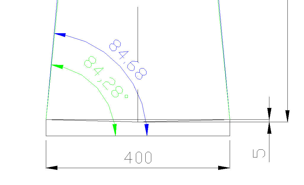
The arrow that you have to dig your primary will have a depth of (DxD/16*F) = (400×400)/(16*2000)= 5mm.
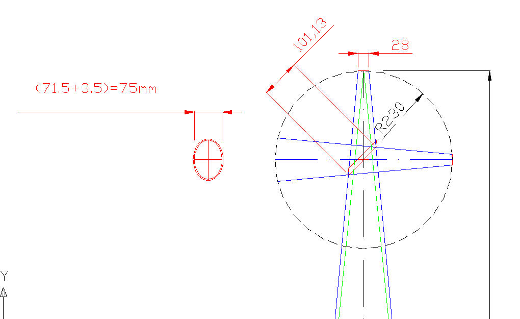
From this central point which lies at the bottom of the groove of the curvature of the primary mirror, exalt your long 2000mm vertical which leads to fire, (dash-dot vertical line).If you wish to impose a 28mm field of full light (that it is the upper limit for eyepieces with a barrel diameter 31,7mm) you have to imagine that a 28mm diameter disc located at the top of your vertical 2000mm (horizontal line in red and listed in red)
The radius of such a disc is (28/2)=14mm, and this radius corresponds to an opening of the cone of light equal to: (Arc tangent of 14/2000)= 0.4 degrees each side ....(see drawing where 84.68 ° is the blue corner of the full light cone of the field, while 84,28 Green is the focal point; whereby 84,68-84,28)= 0.4 ° for part, which will mean having a fully enlightened vision that will embrace 0,8 degrees of sky).
If you suppose to divert the eyepiece such a disc (dash red 28mm) at a distance from the fire vertex on the axis of the telescope, of 215 (distance derived from giving an inner diameter equal to the secondary cage mirror diameter plus approximately one hundredth of the focal length, ie say 30mm, as normally it is done to take into account the divergence of the light beam picked up from the parabolic mirror), it follows that the secondary mirror is necessary to have the larger side of its ellipse equal in length 101,13mm , and therefore its shorter side will be (101,13* root 2)= (101,13*0,707)= Slightly greater than 71,5mm.
But as the plane mirrors can present their worst fault of their flatness along their border, is normally precautionary not use the edge of the mirror but take one that is slightly greater than and equal to the first higher commercial size, which in this case could be 75mm.CLICK ON THE DIRECT LINK TO SEE THE DESIGN MUCH MORE’ ENLARGED ITS PREVIEW
direct:
https://s11.postimg.cc/5yjaa3103/Dimensionam_Secondario_400_F5.jpgdirect:
https://s1.postimg.cc/hlezwqlb3/Zona_primario_400_F5.jpgdirect:
https://s2.postimg.cc/t0clvgw09/Vista_Zona_secondario_400f5.jpg30 July 2017 at 22:54 #10219I realize that I made a mistake in your CAD drawing, bringing the focus eyepiece at a distance from the axis is 230mm instead of the 215 I indicated in the text, so the right side would still be slightly smaller than indicated.

The reasoning general guide does not change, but I apologize numerical incident
.31 July 2017 at 8:30 #10221Finally, thank you! it was quite a while I was trying to come to terms with this elusive “field full light”, I searched on different forums, but no one had ever explained that went IMPOSED according to the eyepiece used. example of how a detail can open up the world
However, Giulio I would advise you to put this article or a similar (obviously weather permitting) in the section “projects and sizing” because I find it extremely useful and it does not seem to have seen it here 1 August 2017 at 8:48 #10222Thanks Marco.
For some’ For I have a draft of such an article to be finished, where they provide two different starting hypothesis: A imposing a precise width of the field in mm, for example derived directly from the FOV of an eye, and assuming one wanted to see simultaneously two separate objects from a certain angle, such as two galaxies or a double star.
We will work after the holidays.
1 August 2017 at 11:49 #10225The CPL study is an interesting topic excellently described by Giulio. I would add another aspect, one of the typical aberrations of the optical system in question, in other words, “correct field” , the area around the optical axis on the focal plane within which the aberrations are “acceptable” and not deteriorate the image quality.
This parameter should be seen in the CPL design in order to optimize the entire system.
A Newton F4 does not have the same correct field of a F6 or any other optical scheme of equal opening .
So in a given optical scheme, some of CPL value could also be functional for the correct field, while for others it may not be.For example the proper head ( or what purports to be ) a Newton 300 F4 will never reach an extension 25 mm focal plane without showing a devastating coma at the edges of the field, so it would not be convenient dimensional CPL with this value because it would not be exploited.
And if this aspect is not conclusive visual observation, become crucial in photography.
An aid to the complete design of the CPL, It can come from the calculation and the simulation of aberrations depending on the schema used with an optical design software, so check what should we expect to see for a given CPL focal plane.
2 August 2017 at 10:40 #10230I must say that the “heaven” It has always been a strong attraction, and again and again I floated the idea to build me a tool to observe, but more into details and more I realize that it's really build complex one that present the fewest defects / aberrations possible…comes always something new to learn and if before I was ignorant enough, now hearing about all these fields etc. I just feel Ignorance himself
-
AuthorPosts
 [/url]
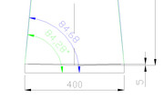 [/url]
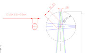 [/url]
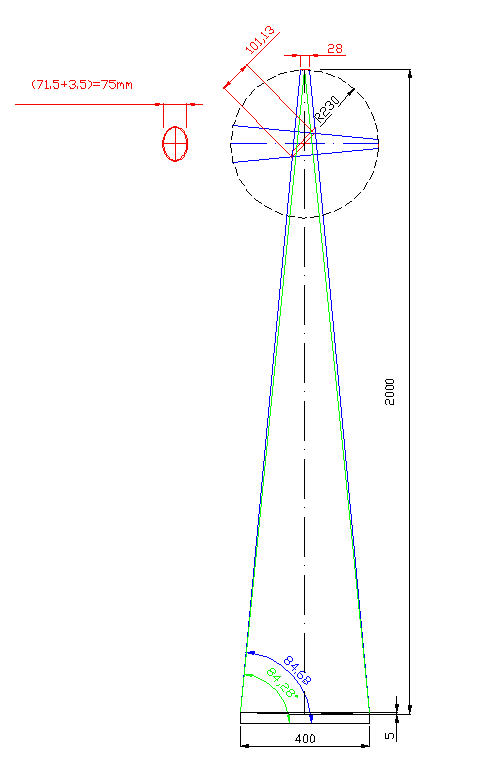
- You must be logged in to reply to this topic.