- This topic has 9 replies, 3 voices, and was last updated 2 years, 9 months ago by
Giulio TiberinI .
-
AuthorPosts
-
5 June 2021 at 7:14 #12256
good evening gentlemen!
It's been a while since we last spoke ... but I'm happy to find you still here.
Unfortunately, the period was not the best and practically all the time was unfairly divided between smart working and the rewarding tasks of a new dad.. Unfortunately, little or fortunately, dedicated to personal projects.
But things are more or less progressing and I also got my nice 500X30, that just looking at it fills the heart with hope, the brain of projects and the eyes of tears ...Anyhow, while I look forward to having a little more time, these days I have the opportunity to start building the Ronchi tester / Foucault. In reality, I have not had the opportunity to approach them theoretically, I just happened to have a couple of days off and I said to myself… come on, I'll do it.
So looking here and there on the net, I have more or less understood where I am headed.
However, I have a couple of doubts that are certainly originated from a lack of in-depth analysis but also from inaccurate if not conflicting information found on the net.
So I was wondering if you could help me understand how to set up the tester. For the sake of brevity and to avoid getting bored, I will make you a list of the points that are not clear to me or for which I found too many dissimilar info:1. I have seen that many use a rather bright green LED and discuss placing a "cap" with a slit in front of the LED.. Others, on the other hand, just ignore the slit cap. There are those who use a last century style light bulb. So I wonder what is the correct technique and which guarantees better results (led, light bulb, fenditura etc ... )
2. I have seen that some place the reticle (thankful) by Ronchi both in front of the observer and in front of the light source, leaving me more than perplexed as to what to do.
3. Some use a laser collimator to position the tester appropriately relative to the mirror. But the question that doesn't make me sleep now is: what is the correct position? I've read about people who arrange the light source and the observer symmetrically with respect to the mirror's axis of symmetry; others that match the observer's position with the mirror's axis of symmetry; finally, still others align the light source with the mirror's axis of symmetry.
4. Regardless of whether the Ronchi lattice interests both the observer and the source or not, and regardless of what I go along with what, it is advisable to arrange the source and the observer so that they are on the right-left of each other, or above-below each other, assuming the lattice is vertical?
In attestation of such a welcome series of explanations, I will certainly delve into the technique as much as possible, but in the meantime, since I'm here where I can be operational, I will proceed in this direction:
1. A green led without cracks
2. I will place the Ronchi grid or Foucault's blade only in front of the observer's eye / camera / camera
3. I will aim the observer with the mirror's axis of symmetry
4. I'll place the source below (circa 2 cm, the name, under) to the eye of the observer, so maybe 2 centimeters below I still put the blade ...
Anyway, whether the progress in the construction of the mirror will continue with the speed held up to now, an eon will pass before I can use the tester ... I will therefore have time to read more and more but above all to receive your advice.
thanks a lot
Alberto8 June 2021 at 23:53 #12257Hi Alberto,
happy to re-read you here in the blog and congratulations for the new dad
First of all, I am attaching the links to three articles written by Giulio and Enrico present here on the site, all referring to the construction and use of the ronchi / foucault tester.
I try to answer point by point:
1) the sites that report the use of old incandescent bulbs is because they are a bit dated, nowadays it is usual to use simple green LEDs (They don't even need to be particularly bright).
2)Personally in the ronchi test I place the crack (made with two fine sharpened penknife blades) in front of the source and the grating only in front of the eye or the camera (obviously with the lines parallel to the crack).
3)The laser pointer for collimation is not essential, for example I don't use it. Then, first of all, you need to position yourself with the light source approximately in the center of curvature of the mirror or twice the focal length. After that, if the light source is placed just to the left of the optical axis of the mirror, the reflected light will end up just to the right of the optical axis, if you put it just under the reflection it will end as soon as sora, and so on. The important thing is to keep the distance between the light source and the return beam as low as possible, 1-2 cm at the most (obviously the returning light beam must pass through the ronchi grating). For the foucault, on the other hand, a blade that half covers it must be placed before the LED. The blade itself should protrude a couple of centimeters above the LED. The light returning from the mirror must be intercepted by this source part of the blades. This ensures parallelism between the source blade and the test blade.
4)I personally prefer the source below and the lattice just above. In this way, I minimize the introduction of astigmatism in the test as much as possible.That said, I agree with the procedure you have decided to undertake, apart with the dot 1 in which you say not to put the slit in front of the LED. That crack is crucial. In principle, the ideal width of the slit should be of the order of magnitude of the spacing of the lines in the ronchi lattice (generally 50-150 microns of bene).
I hope I was helpful…See you soon
Ciaooo 15 June 2021 at 22:46 #12258
Hi Alberto.
Your doubts are the normal ones for all people who think about facing the making of a mirror.
In fact, each of the choices that lead to doubt, it is a prerogative dictated by the needs of one test or the other (speaking of the Ronchi and or of the Foucault), and from the resolution of the data provided.
Very low resolution in Ronchi and very high in Foucault, so it is better to start with the Ronchi but finish a mirror F5 or higher, with Foucault.Here I try to summarize the parts most targeted to your doubts, from the articles of the indicated links.
To highlight the fundamentals of the two tests Ronchi and Foucault:The objective of a Newtonian reflecting telescope must be a parabolic mirror, to bring the light rays that will make up the image of a stellar object placed at infinity into a single focal point.
It is a question of making a “revolution” parabola which is obtained by making the curvature on the mirror, walking around him around a table.At first, establishing the desired focal length (which is equal to twice the radius of curvature that the initial sphere must have) is obtained (always aided by the revolution of walking around while working) a spherical cap having "depth" (said arrow) generally a few millimeters, carved into the center of the glass, which after refining and will then be "flared" in polishing, (generally a few microns) however having parabolic progression (like the theoretical parable taken as a constructive reference), starting from the center and up to the edge.
Let's say immediately that the Ronchi and Foucault tests are done by positioning the lattice of one, or the blade from the other's knife, to the distance of the radius of curvature of the initial sphere.
And we also say that the Ronchi lattice places the center of the radius of curvature of the initial sphere…if the sphere is a good sphere…it will show the entire surface with many lines (if you are away from the fire) or a few lines (if you are close to the fire), But the lattice lines will not appear deformed, then straight,. Or vice versa curves in the presence of a "hump" or curves in the opposite direction in the presence of a hole, reversing the position from intra to extra focus and vice versa. And therefore it is understood the correction to be implemented, but it is not known how much the defect is to regulate the duration of the correction. Also in the test you can see the lines of the lattice that are distant from each other, if it fits only 0.1mm.
The Foucault test could also be carried out at the same point as the Ronchi, on some pairs of windows open on different circular crowns. (The measurement made on the diameter of a surface made by "revolution" is by definition considered equal to any other diameter of the same surface).
The only difference is that the Foucault test provides graphs with the slope of the workable areas, and the amount in nanometers of the error, which facilitate the estimation of the severity of the correction to be applied, with a resolution of approx 600 a thousand times more sensitive than the Ronchi.
But the threshold of the minimum quality of a mirror because it can be considered limited only by the diffraction of light, and of 68,75 millionths of a millimeter between peak and valley of the maximum residual roughness.
Here is therefore a non-exhaustive reason, but consistent with possibly carrying out the tests in conditions just outside the diffraction limit, using as a light source NOT a naked Led (source too large and roughly distant from the diffraction) but not even a pinhole (very difficult to make with a diameter of 2 or 5 hundredths of a millimeter), that also so small would reduce the brightness of the LED too much, But making an easy crack, which has the same physical behavior as the pinhole because it is wide 2 cents, but it is much brighter because it is "high" 4mm in front of the LED.
And to make a wide slit 2 or 5 hundredths of a millimeter, just fix with double-sided tape, two razor blades with the cutting edges facing each other and separated by a spacer consisting of a small piece of magnetic tape from a videotape, which has precisely that thickness.
And the plate is then easy to put on and remove from in front of the led, to trace its luminous dot reflected from the mirror, and aligning the tester, bring it to the Ronchi lattice, or on Foucault's knife.The width of the slit is not mandatory, as well as the low sensitivity of the Ronchi, because a certain bad behavior can also be sensed with the Ronchi test, showing errors across the entire surface, even if sometimes imperceptible due to the low resolution compared to Foucault.
The ideal is to use both of them but finish the mirror with Foucault, (Up to focal ratio F5.
7 July 2021 at 14:11 #12261Thanks for the replies…
as soon as I have a moment I will read them with eager attention. I had already read the contents of the linked pages – and many others, however doubts remained. Already scrolling through the text of your answers, I know I have to foresee the crack
I count this weekend to be able to dedicate a few hours to the project and then finish the construction of my R-F tester. Then if I can finish it, I post it, if I find out how…
Thank you very much and see you soon
A9 July 2021 at 0:13 #12262Well Alberto,
If I remember correctly the process, even here you can upload the images first uploaded to a host from images such as POSTIMAGE, which tells you to choose the image to upload that you will select on your computer, and after loading, gives you the choice between different types of links.You choose the link of “preview for forums”, click copy, and then here you will paste it where the blinking cursor is, in the window that will open by clicking on the blue square with the writing “img”.
That type of link will show the preview image, giving the reader the possibility to enlarge it with a click, and even further with a further click on a cursor by the sign +To read you again soon|
Ciao
Giulio.27 July 2021 at 8:57 #12268good morning ladies and gentlemen
first of all, thank you again for all the advice I have scrupulously followed in “to design” he test.
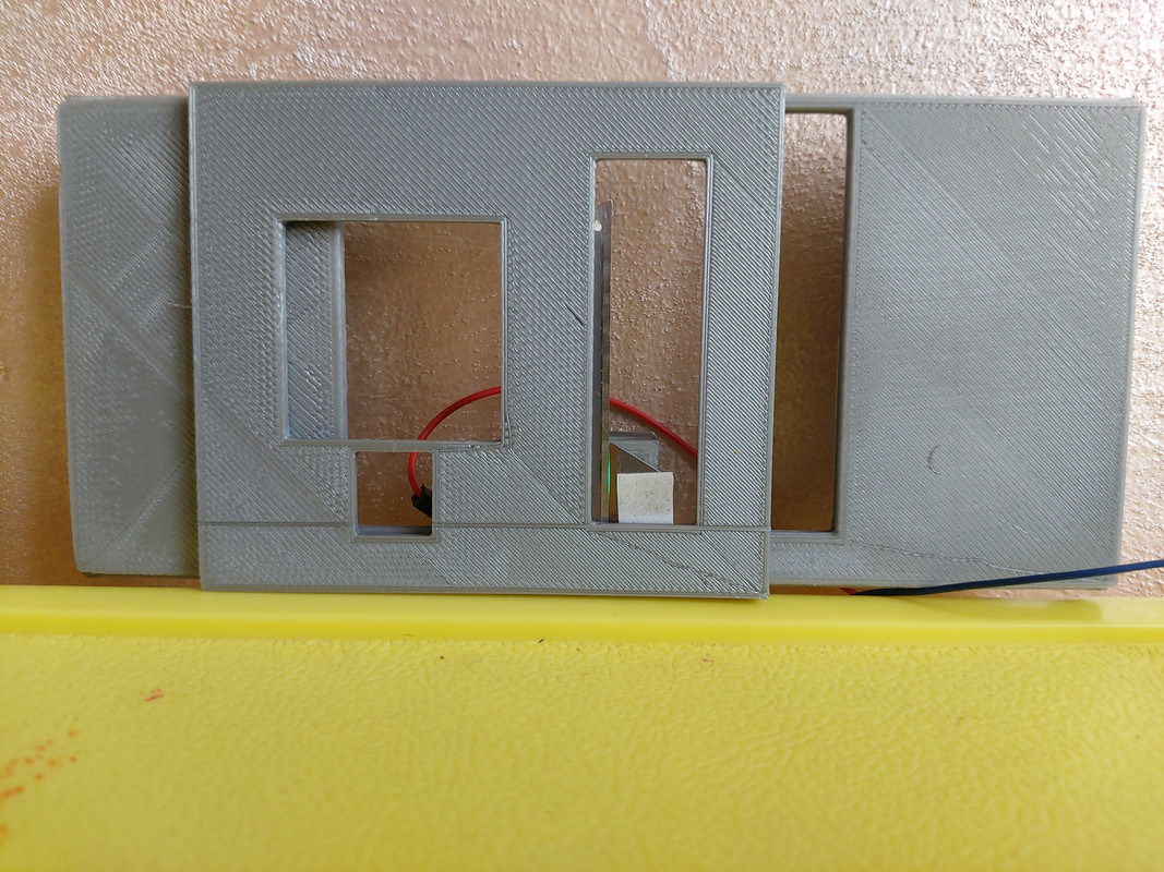
Unfortunately, I didn't have too much time to turn the project into object, and what little I managed to do I have not had the opportunity to test it since, Attila, which is not my son's real name but it should be, as soon as he sees a tool, he mistakes it for a Roman camp… On the other hand, I managed to mount protractors on my Dobsonian. The supports for the hands, li ho stampati 3d, mentre i goniometri Az / Al were printed 2d on paper and pasted on cardboard. Within seconds I was able to aim for M51, glimpsing something (I fear my 150mm won't allow me too much… ) and I would say that the aiming system works with dignity, considering the time invested. To do the math on the fly, I also made an android application (an exercise more than a need) works , chosen as a reference the object currently pointed to, it tells me in real time how much to vary az and al to point to the new object.Anyhow, returning to the tester, i managed to print 3d (I draw at night and the printer is inaccessible in the autumn) the mask where I placed both the openings to view the mirror and the blade support (those of a cutter properly rubbed against the glass) which I use to get the crack. They are mounted on a slider, bound to the mask, which allows me to easily switch from the Foucault configuration to the Ronchi. I would have liked so much to disassemble the primary 150mm 7.8f of my dobson for “see the effect it has”, but I was afraid to finish the test without even a mirror (all 16 the puppy wakes up). Then, just to understand what happens, I electrified the slider with a green led (it seems to me a 3v 60 ° that I had bought on another occasion) and I pointed the mask against a wall, at a distance of a few decimetres, otherwise you could not even see the LED light. A figure has formed which unfortunately I expected but which I do not understand if it is correct for the purposes of the test. It more or less consisted of three vertical fringes “|||”. The central fringe, clear and rather defined, it was clearly that of the cleft (obtained using a thin film as a thickness gauge, very thin, than what I had – I have not found a magnetic tape but I will get it) while the other two external ones were more or less shaped like “D” (right) and of “D mirrored” (left). Geometrically the thing comes back, but I wonder if the result is correct and if something is not wrong. What do you think about it? There is a way to understand if I am on the right track without disassembling the primary (which I will do next episode but I would like to get there ready) in placing the blades and creating the slot?
As always, thank you and forgive me for all these questions, but the short time forces me to try to get ready for the practical work sessions and to have to minimize the experimentation in the field.
Alberto
Below is a photo of the mask and the slider with the blades (no Ronchi)
 27 July 2021 at 9:02 #12269
I don't have a clear idea of how the image post works but it seems a bit’ little one posted above (I followed the instructions but I can't click anywhere to enlarge it). I try to put the direct link: https://i.postimg.cc/TPm8JJkr/20210727-084851.jpg hoping it works
31 July 2021 at 17:46 #12270Hi Alberto. Sorry for the delay, but I was on vacation for a few days.
you say:
I managed to mount protractors on my dobsonian. The supports for the hands, li ho stampati 3d, mentre i goniometri Az / Al were printed 2d on paper and pasted on cardboard. Within seconds I was able to aim for M51, glimpsing something (I'm afraid my 150mm won't allow me too much ... ) and I would say that the aiming system works with dignity, considering the time invested. To do the math on the fly, I also made an android application (an exercise more than a need) works , chosen as a reference the object currently pointed to, it tells me in real time how much to vary az and al to point to the new object.Well…here you deserve compliments. Why did you make yourself gods “digital circles” much more performing, thanks to your smart Android application which is a niche gem. Bravo! (I was left out with the programming, since that was born “to objects”)
What about the tester for the Foucault and Ronchi tests…Here too you are doing very well, because a sliding support that allows you to exchange the Fouvcault blade with the Ronchi reticle, back and forth in front of the same slit, it's a convenience, which among other things, whether your construction will have the vertical slit of the blade or lattice, allows you to test without removing the mirror from your telescope.
Just place the rubo 150F7 horizontally in front of the tester, the distance from the center of curvature of the mirror, which in your case (150F7) è a 2100mm (twice the focal length).
The slit will illuminate the mirror inside the tube for both types of tests.As for the ratings, the tester must be used with the mirror. the slit itself is a very bright vertical line even if very thin. The images of the backlighting of the mirror acquire interest. It would agree that you include them in your posts, in order to be able to evaluate them visually.
To insert them you can use that Postimages.org you have already used; Upload the image from your computer choosing not to scale it. After that, in a position below the insertion area, where you will see a list of many links applicable in different ways, choose the link “for forum preview”, to be glued into your interventions.
That type of link allows those who see a preview of your post, to enlarge it as you can see with the direct address, that is often full screen, clicking on it with the mouse.Hi Alberto
Giulio5 August 2021 at 13:24 #12278hello Giulio
thank you for the tip. I didn't actually try to use the telescope fearing that the secondary supports would prevent the test.
I hope to succeed, next week, to terminate my tester. I have all the pieces now, I just have to find the time to assemble them.See you soon
A7 August 2021 at 0:35 #12279Well. See you soon
Ciao
Giulio -
AuthorPosts

- You must be logged in to reply to this topic.