PART FOUR AND LAST:
NOTE: Clicking on the images You gets his magnification, often helpful to appreciate the details that are in practice the object of this work.
(All images can be enlarged with a click)
Today is the 7 March 2009 STARTS POLISHING
I take the job Amateur abandoned 4 February for "paid" business reasons .
I so resume the mirror whose surface was evenly grained satin from abrasive 800
I will try to use the first to the energetic abrasive Zirconium Oxide, diluting a table spoon with two tablespoons of water in a jar, brushing it on the object that in turn is on the table, starting with the tool under, and mirror above.

First of all, in the process of polishing with pitch (as well as in phase of parabolization) is ALWAYS NECESSARY TO HAND PRESS in contact for a few minutes, the garnished abrasive tool on the mirror, turning and pressing a few times.
This pressing is indispensable because the machining tolerances ranging clutching at lower values of 68.75 millionths of a millimeter, and therefore the perfect contact and adjustment tool to shape the mirror, is crucial to improve a difficult job, that without meticulous attention, It is likely to get worse.
A further important caveat to keep in mind FOR not to get out of the machining tolerances, species in parabolization, is to try not to load un the moving object, (mirror or tool that you have in hand,) , with the weight of the hands., But instead drag as much as possible, back and forth by pulling or pushing it to the edge..
With mirrors thin this is not easy, but you can.
After one hour of work with the usual strokes with protruding 1/3 diameter (1/6 back and + 1/6 and forth), the mirror has well-polished a wide circular crown 3 cm, while the center and the periphery are still satined (see photo (clik to enlarge)).
After one hour of work, the glazing of the abrasive 800, gave way at the first hint there of reflected ceiling with 2 neon tubes, on the circular crown to 70% diameter. (click on to enlarge)
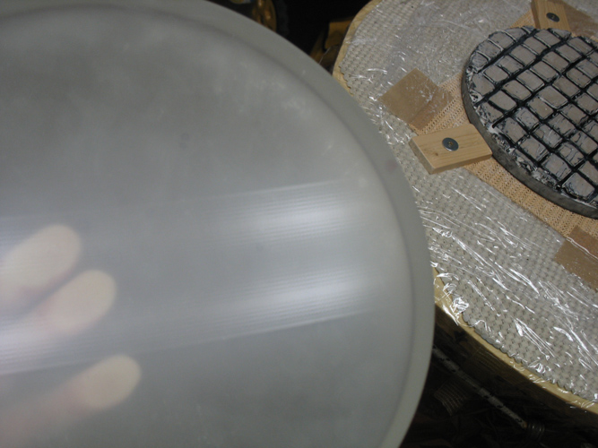
I change location by placing a mirror underneath and work for two-times 45 minutes each. the past 90 minutes check again the mirror that is completely polished and transparent (see photo (clik to enlarge)).

..After another 90′ polishing, the reflection of the ceiling has the smallest detail
SHORT NOTES ON THE DEGREE OF TRANSPARENCY REQUIRED FOR OPTICAL MIRRORS.
The supposedly good gloss visible in this photo is however hardly obtained but is low compared to what you have to reach to act as a telescope optics.
Indeed, the telescope is capable of forming at its focus an image of a small object that is at the infinite.
For example, the planet Saturn, whose only disk without the rings subtends an angle of 20 arc-seconds, when it will be seen with a telescope that will use this focal mirror 1268mm, give a picture of the focus with size of 0.12 mm in diameter. Dues to::
focal mirror in mm * (arc subtended by Saturn in arcseconds / 206265 arcseconds per radian) = 1268*(20/206265) = 0.12 mm diametro
An image so small it must be very full magnified with an eyepiece to observe in its details.
But the eyepiece in magnifing strongly the image, magnify also strongly the faults of mirror surface.
CLOSED THE NOTES ON THE DEGREE OF TRANSPARENCY
BACK TO WORK:
I test the mirror at he Sun light to approximate its focal length, applying variant with solar illumination source, instead of a battery-powered torch (see movie of the same method ) It measures in 1243mm equivalent to F 4,972. I review the grooves on the tool with the blitz welder, running off the pitch on a teflon sheet to recycles it.
Given the level of gloss achieved, I decide to make the first test of Foucault without Couder mask, just to see to more accurately measure the focal lenght, and I find a radius of curvature equal to 2520mm which corresponds to the focal 1260 equal to F 5.04 …..Exclamation positive!
The trend of mirror surface, in comparison with the trend of the parabolic curve keep as reference, computed on the focal lenght just measured, comes with the Center and the edge releved compared to an area at 70% diameter that is much better , like is canonical for a smooth spheroid which must become parable.
But there is little clear halo, which is the infamous roughness infinitesimal, visible to the Foucault test as a “cloudiness” central just lighter than the background of the mirror (French phenomenon called "mammellonage"). Which means that my 17 ° Operating temperature is too low , or that the pitch is too hard for the working temperature.
Of course I decide it is cheaper to heat a little the room with an electric heater to work at 20°, rather than redoing the tool with the other pitch.
For now I close my jobs.
Time spent in polishing 2 hours 30 ' (2.5 decimal hours) t ° to 17 ° c.
Total time work = 16,5 decimal hours
Today is the 9 March 2009
The electric fan heater brings me soon t ° environment 20 ° and I resume the work to combat the glazing roughness central, beginning to see what will happen after an hour of work putting mirror over ...... Recalling that the universal rule for "grattavetro" (Glass scratcher) says:
- That with the mirror ABOVE, He digs the mirror center (until the 70% diameter) not touching the edge;
- As with the mirror UNDER, It dig the edge (from the 70% diameter onwards) not touching the center.
This time I will use that abrasive named OPALINE (refined Cerium oxide ).
Since I have other commitments looming, but I want to continue with this work, I decide to shorten the time by pressing the tool fit on the mirror, not at room temperature but "bain-marie", ie immersion of all in a basin of water at 35 ° c, verifying what happens after a few minutes.
The cerium oxide, contrary zirconium oxide, It becomes effervescent after 30 'of work, but the adherence is tearing, and it makes the very hard work. Which makes me think that at this stage of the process should be more diluted the abrasive, passing for example from the current ratio Cerio / water = 1 until 2; to a cerium ratio / water = 1 until 3.

The desired foam produced cerium oxide, that between the pitch squares it promotes the circulation of the abrasive
After an hour of work with the usual strokes 1/3 diameter, Test well on the gloss surface, that 100x magnifications microscope shows a residual dispersion of about 2 small craters for each division by 20 microns of the grating.
I quit the job after 1 hour
Total time polishing = 3.5 decimal hours
Total time work = 17.5 ore “ ”
CURIOUS NOTES ON “WHISTLES” from the TOOL and consequential IRIDESCENCE on the glass.
The argument “Whistles and iridescence” It is very interesting, and is rightfully inserted into the advanced polishing stage.
In the processing of my 250F5 Pyrex was happened (well to me) to produce a tenuous “rainbow” on the mirror surface. And this was happened following my want to try to "pull" at maximum the "wets" with cerium oxide, until cause the tool whistling.
In fact we read also on the book of Texereau “LA CONSTRUCTION DU TELESCOPE D' AMATEUR”, in subparagraph 25 “polishing of Conduct” (in my edition on page 47), that the high-pitched whistle that arrives to warn the literal drying water in a end of a wet (When the polishing process is well under way for more than half hour of work), is a good sign that indicates the maximum efficiency in abrasion ... ..But I realized that there is not an attitude to hold for longtime, and I am self-convinced that that whistle at a certain frequency (to understand each other, suppose a 2 thousand hertz) , It is the expression of a "chain stop and go" due (for example 2000 times per second) to as many seizures of elasticity of dryed pitch, and immediate new "snap departures".
It is an oscillatory phenomenon that starts and automatically feeds itself after the first stop & go, repeating identical as long as you keep the same speed of movement.
And I believe that the appearance of the soft rainbow visa later on the surface of the mirror, it were “the recording” on the glass of the whistle phenomenon, that scarce water, suppose has generated a series of micro-roughness imprinted in the glass at the same acoustic frequency.
Roughness that produced in constant rows ordered by the straight line movement is basically a pattern Reticle embossed into the glass from the tool.
Reticle that as such, it creates the effect of decomposition of light in the colors of the iris (how does a CD-Rom, or a lattice from 600 lines / mm for a spectrometer), acting with the light in a manner equivalent to a prism.
I have realized that it is not a bad thing to whistle the tool as the saying Texereau, to encourage the elimination of many craters as a result of the famous hypothesized “of molten glass transport” at molecular level, at that time becomes the maximum. But after the whistles, observing possible slight iridescence, need some quiet time wets, spent to clear these micro-roughnesses generated on the surface.
Of course these are my conclusions gained with the "mind on my hands", working my mirror, but with the memory in my workshop as the tool of a lathe whistled, and turning done in that way could not smooth, but jagged because perceptibly vibrated.
Today is the 10 March 2009
I warm the environment at 20 ° with electric heater, I clean the channels of the tool with the soldering gun pistol (welder blitz), and run it again pressing mirror-tool dive in water to about 35-40 ° c.
I'll be back Zirconium Oxide this time in relation diluisco 1 until 3 oxide with a spoon for three tablespoons of water.
I find improved grip and rolling resistance that make me work with less effort. Work alternating dried with mirror above and below. following, with the microscope and illumination from the rear mirror, I see very few craters gray, and almost only in the center of the mirror.
I control then the entire surface roughness with Foucault without Couder mask, and I find the mirror-free spots, sign that the infinitesimal surface roughness was canceled.
I check with Foucault the difference between focal from the center and the edge of the mirror, and read:
edge 62.53mm
center 61.27mm
The difference is 1.26mm: Result that suggests to me that:
- Considering that for a mirror 250F5 perfectly parabolized must be 5.16 mm
- and Whereas, if the surface was made instead like a perfect sphere, this difference in focale between center and edge should be zero,
Having Me measured the difference 1,26 mm, I find myself having generated a curve that is already slightly flared towards the parable.
I am, however, much closer to zero than to 5.16, : Ie, close to the sphere rather than the parable.
Which is good sign that in the work I have good content swiveling towards the "right and left", thereby avoiding too countersink my curve.
It would indeed have been much worse if my draft board from center mirror, was greater than 5.16 mm, and thereby demonstrated to have already passed the curvature of the parabola, it would therefore already become a hyperbole unusable in a Newtonian telescope.
Such an error would have forced me to a “game over” , ie to imposssibility to work for overcoming the tolerance.
In that case the only thing possible before resuming a new parabolizzazione, is back towards the sphere with a few hours of work by applying strokes 1/3 diameter, but taking care at work, to not exceed more than one centimeter in swiveling left-right.
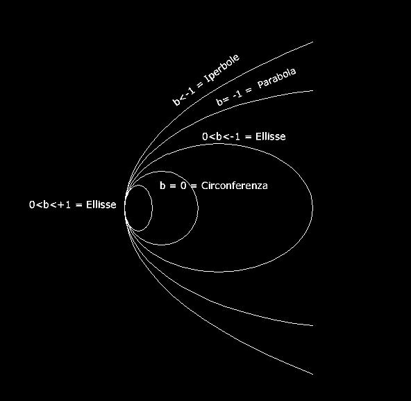
(See in this respect the progressive conical curves family that you can inadvertently encounter scraping the glass, depending on the deformation coefficient between the values b +1 and less than -1, often introduced in the formulas).

Work time 1 hour: Happy of my work, I wash all, I wipe the mirror back and postpone for tomorrow the resumption of work.
Total time polishing = 4h 30′ (4,5 decimal hours)
Total time work = 18h 30′ (18.5 decimal hours)
Today is 2009 March 11 2009
Local heating to 20 °C - Pressing mirror and tool "bain-marie" at about 40 °C - Dilution zirconium oxide / water = 1/3
Finally the 100x microscope I see in the center about 1 Crater dot every different divisions of my lattice by two hundredths of a mm square , while towards the edge of the mirror they are much rarer.
Based on what the book says Le Cleire (2) "Realisez votre telescope" on page 152, for a mirror 250mm serving about 6 Polishing working hours, and having I employed 5.75 (ie 5h and 45 '), neophyte think I behaved well, and also to have come almost at your destination for the start of the stage parabolizzazione.
Work Time 1h 15 ' (= Decimal 1,25h):
Happy of my work, I wash everything back tomorrow.
Total time polishing = 5.75 decimal hours
Total time work = 19.75 ore “ “
Today is the 12 March 2009
Local heating at 20 ° c - Re-opening of some narrow grooves tool - Location mirror under – Pressing a bain-marie at 40 ° C for 1 minute with 5kg weight + various other dry compressions, with both hands for 20 "each, rotating the tool to each of a fraction of a turn on the mirror - Dilution of zirconium oxide / water = 1/3
Since using the continuous zirconium oxide not to encounter the foam production, which will produce the cerium oxide. In the last quarter of an hour I tried to stretch the abrasive with a little water and one or two drops of detergent for dishes
excellent result that produces the desired foam capable of continuously transporting the abrasive pad on the pitch, with the surprising result that the wets last 5 times as much.
Examination of the difference in focal lenght center-edge with Foucault I find that the previous value of -1.26 It rose to -1.86
Work Time 1h 15 ' (= Decimal 1,25h):
Total time polishing = 7 hour
Total time work = 21 hour
Today is the 13 March 2009
I DECIDE TO START PARABOLIZZAZIONE
Then I measure the current true diameter of the mirror , that the bevel is currently become erosion 252mm.
I prepare a Couder mask to 6 zones, each with the following outer radius:
Zone1 = 51mm; zone 2 = 72mm; zone 3 = 89mm; Zone 4 = 102mm; zone 5 = 116mm; zone 6 = 126mm
I start the first test of Foucault looking the "grey flat" of the area 1, which turns out to have a radius of curvature of 2535 mm = 1267mm focal = Ratio F 5.07
I transcribe in the calculation program for Foucault test, this true diameter of the mirror; end a Zones data by the Couder mask, and the exact focal lenght measured.
And then I run the first set of two measurements by each Zone (one going outward from the zone 1 to the 6; and one in return backward from Zone 6 to a 1), Two numbersa that mediated, provides the following first drawdowns to be included in my spreadsheet:
zone 1 = 56.75 ; z2 = 57.05; z3 = 57.72; z4 = 58.19; z5 = 58.61; z6 = 58.41
These values included in my spreadsheet to Foucault's test, are showing me the graph of a balanced surface (having approximately the same values of aberration at the center and at the edge passing by a good "middle" at diameter ~70% of the mirror) wich is the classic initial shape; too high at the center (zone 1) of 303 nanometers high.; good in Zone 4, and too high at the edge (zone 6) of 311 nanometers high..
The sequence of measures Readings found in all 17 Foucault tests relating to 16 tweaks correction that led me to finish the mirror, It is contained in the following table, and it can be useful to any interested reader, you can insert them into a software for the Foucault test management (for example the well-known "FigureXP") materially to see the evolution of the shape of the surface, from the initial one that ended with an error peak / valley of the best mirror of Lambda / 10 of the wavelength 550 nanometers high., also while meeting the criterion of Couder which imposes to merge all the reflected rays in the foci (that is at the distance of 1267mm from the mirror), making all them converge within the notch diffraction of the instrument, which has a diameter 6.8 microns.
This policy ensures that the diffraction notch will be seen doing the star to the telescope test, has the “canonical form” which concentrates at its midpoint 84 % light, while in the first ring it only concentrates 7 %. and in the second the 3%, and the remaining 6% in the outer rings. Which means get maximum contrast from the mirror.
Indeed, if this criterion was not met, namely some areas go to reflect OUT of the diffraction notch, not participating in this way to its formation, It would result in a transfer of a certain amount of light from the center point toward the first outer diffraction ring. This transfer produces the effect of enlarging the diameter of the central spot to form a “stain” wider comprising the first diffraction ring, and therefore less bright, Lose contrast and resolving power to the vision through the telescope.
NOTE: References to types of races entered (as aII going to a2; AIII going to a3 etc.) in the following table, to be applied in tweaks correction of the various types of defects encountered in the various zones Z of the mirror, refer to the nomenclature shown in the table / image published on page 81 Jean Texereau frech book entitled “La construction du telescope d'amateur”, for convenience of understanding, also posted the end of this article.
| First verification | Lambda/0.9 | 56.75 | 57.05 | 57.72 | 58.19 | 58.61 | 58.41 |
| 0 – Starting Size 13/3/2009 | Lambda/0.9 | 69.58 | 70.01 | 70.29 | 70.88 | 71.40 | 71.17 |
| 1° Retouching: Lowering middle: 7′ W strokes type IIA | Lambda/0,9 | 69.22 | 69.64 | 70.25 | 70.76 | 71.37 | 70.96 |
| 2° Retouch Lowering Center: 15′ W strokes type IIA | Lambda/1,2 | 67.11 | 67.79 | 68.26 | 69.17 | 69.77 | 69.54 |
| 3° Retouch Lowering Center:15′ W strokes type IIA | Lambda/1,9 | 61.77 | 62.99 | 64.03 | 65.06 | 65.63 | 65.57 |
| 4° = 2 table runs Remodeling zone 6 for falling border with strokes W type aIII | Lambda/2,6 | 63.11 | 64.10 | 64.86 | 65.99 | 67.03 | 67.00 |
| 5° = 3 laps Remodeling discount table Zone 6 (Corse W aIII)+1 He ran around the table W type cII | Lambda/1,6 | 62.06 | 62.92 | 64.15 | 64.44 | 65.06 | 65.97 |
| 6Retouching ° = 2 revolutions table – downward Zone 6 | Lambda/3.6 | 61.55 | 62.99 | 64.33 | 64.82 | 65.75 | 66.47 |
| 7Retouching ° = 1 turn table – W type c strokes – with mirror above | Lambda/3.1 | 63.31 | 64.18 | 65.46 | 65.99 | 66.71 | 68.20 |
| 8° 2 table laps = Retouching on Z6 with mirror down 1 table lap – W type c strokes, and mirror above. | Lambda/5.7 | 61.81 | 63.35 | 64.09 | 64.95 | 65.87 | 67.36 |
| 9° = 2 table runs Remodeling zone 6 mirror under 1 lap strokes in W c type, and mirror above | Lambda/3,5 | 61.13 | 62.35 | 63.37 | 64.04 | 64.78 | 66.63 |
| 10° = Retouching back to the sphere with 1/3D c.o.c strokes, centrate:1 lap mirror above 2laps mirror under | Lambda/4 | 61.41 | 62.81 | 63.70 | 64.40 | 65.22 | 66.88 |
| 11° = 1/3D return back to the sphere, centrate: 2 Mirror above laps + 2 rpm mirror under | Lambda/4.4 | 59.62 | 60.93 | 62.02 | 62.51 | 63.57 | 65.00 |
| 12° = 1/3D return back to the sphere, centrate: 2 Mirror above laps + 2 rpm mirror under | Lambda/3.1 | 61.31 | 62.40 | 63.42 | 63.66 | 65.20 | 66.84 |
| 13° = Attack Turned Down Edge digging Z4 and Z8 5; 7′ mirror under + 2 laps in W - strokes type IIA | Lambda/4.2 | 60.96 | 62.38 | 63.28 | 64.19 | 64.75 | 66.65 |
| 14° Retouching: Lowering zone 5; Mirror under- strokes centered and forward-backward overflow max 1,5 cm; | Lambda/7.9 | 62.45 | 63.89 | 65.01 | 65.85 | 66.87 | 68.44 |
| 15Retouching ° Z5 = 4′ mirror under – Racing centered and ooze back and forth 1.5cm; | Lambda/6.5 | 63.55 | 64.48 | 65.69 | 66.46 | 67.45 | 68.90 |
| 16° Retouching: Recovery light TDE with overpressure from the Center to Zone 5 | Lambda/5.7 | 58.94 | 59.88 | 60.60 | 61.84 | 62.80 | 64.03 |
| 17° Retouching: Lowering center mirror and just a bit the edge with overpressure, all without touching Zones 4 e 5 | Lambda/11.9 | 58.50 | 59.84 | 60.61 | 61.84 | 62.80 | 63.80 |
The data in this table are the same ones that appear in the gray table below in the following picture of the entire spreadsheet to the test of Foucault, of which one sees some enlargements in the following pictures.
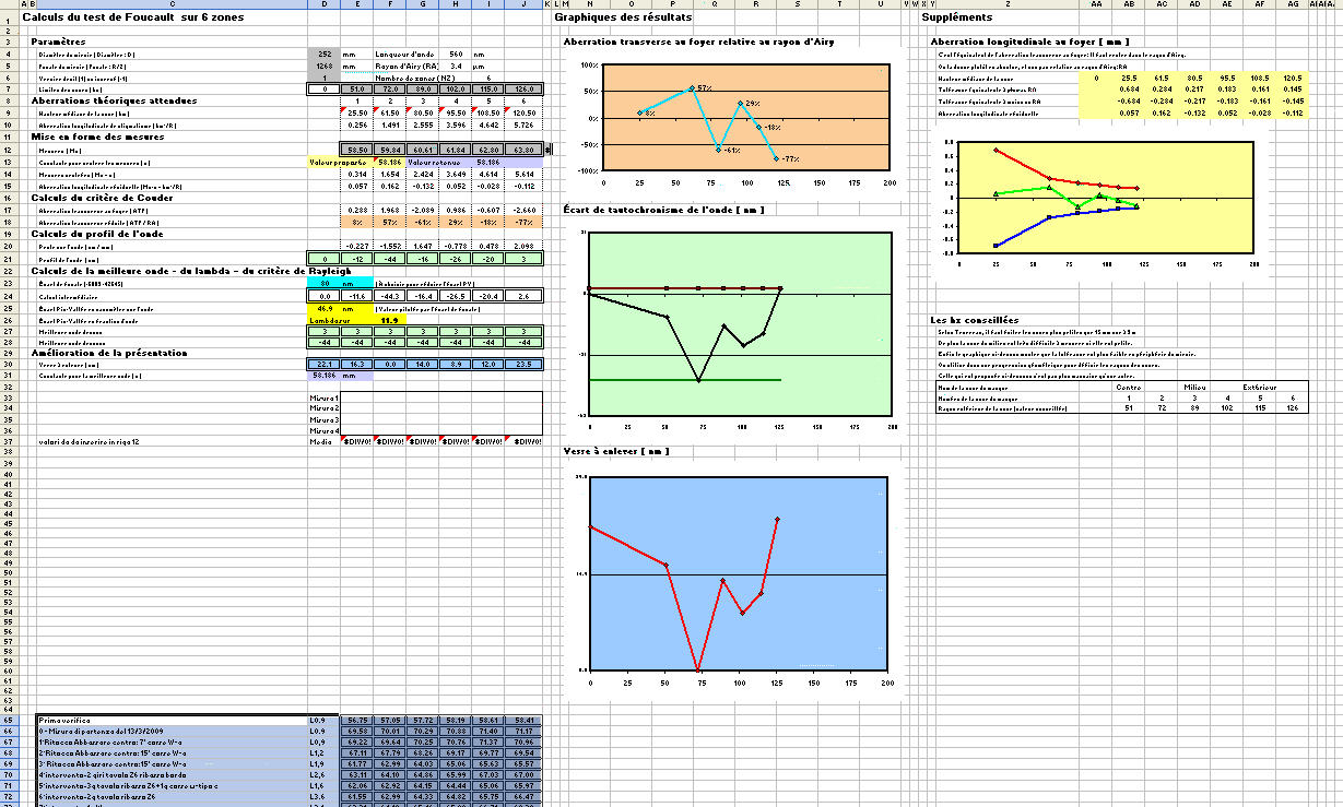
The following picture is a partial enlargement of the previous, and shows the graphs of the mirror final test.
The orange background in the vertical graph represents the amplitude % the mirror diffraction notch, showing inside the reflex points of the distribution of all 6 Mirror areas. Which it is to meet the criterion Couder ;
while the yellow background graph indicates the trend of the tolerances of the various zones of the mirror (points of the broken green line) within tolerances, looser at the center mirror (the left side of the graph), and more restricted to the edge (right side of the graph).
The good thing is that all 6 the points of the broken green that represents the mirror areas measured, fall within the manufacturing tolerances delimited from the two parables, red in up, and blue in down.

magnification 1
Finally the following enlargement shows the graph of green background trends peak / valley of the half mirror surface (The center is on the left and the edge is right). The error peak / valley is represented by the distance between the two copies of the delimiting reference parable (upper and lower red line green) which it is to be given 46.9 nanometers high., or lambda / 11.9 with respect to the wavelength of 560 nm of yellow-green light which the human eye is more sensitive.
In other words, the parable realized differs from the reference parabola for a value of almost 47 millionths of a millimeter.
Which, for a test done by an amateur like me, I do not think it is to be taken as a certain value or absolute,(and this is due to various reasons subjectivity plaguing the Foucault test), but it still represents an excellent result, because although they can have an error of a few percent, It is significant for a better reflection of the majority of those mounted in the commercial telescope.
In the blue background graphic it is quantified the thickness in nanometers that may still be removed to improve the surface further, but ....I am very happy to abstain from doing.
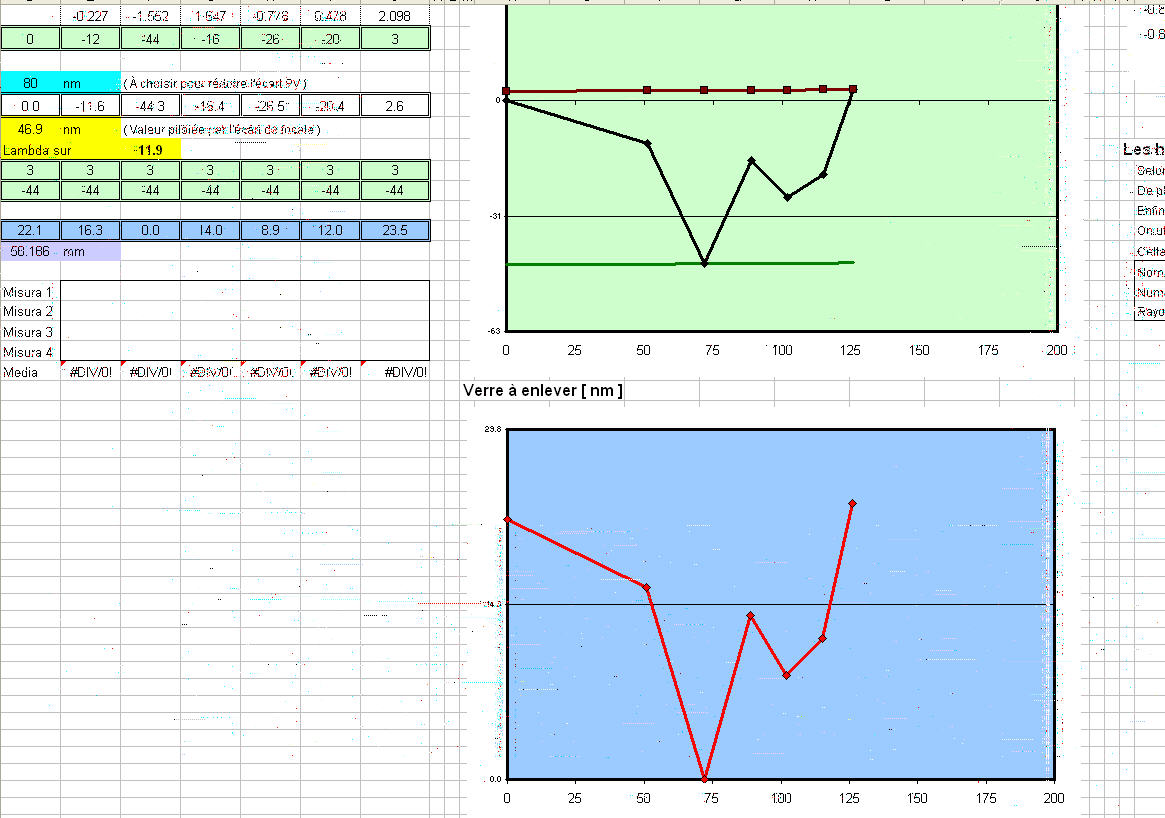
magnification 2
The following image shows the classification types of strokes to retouch the parabole, applicable with tool wirh a full mirror diameter, published on page 81 Jean Texereau frech book entitled “La construction du telescope d'amateur”.

TIME NECESSARY FOR THE REALIZATION:
The time necessary to complete this mirror is the sum of the time spent before the parabolizzation (21 hour) with the time taken to perform the 16 retouchs and 17 tests, I could assess 10 total hours, For a total weight of 31 actual work hours.
Note that in parabolizzation must perform retouching and then wash wipe the mirror and put it on the stand for the test, but test must take place only after the mirror is conditioned losing the thermal expansion due to heating by friction work, and also for contact with the hot hands of the operator.
The question how long to wait acclimatization necessary, I have solved my comfort and safety, waiting "tout court" 24 hour, both for normal glass that for the pyrex. Although the latter would be enough for a less waiting time, for example proportional to the difference between the values of the expansion coefficients of Pyrex glass and the normal.
At the time when I realized this mirror I much wanted to find a work diary, in order to have an idea of the practical problems I was going to encounter.
So I hope that those few daredevils who are come to read up to here, can reap all the benefit that I would they wish, if not other, only to increase knowledge derived from the proven profused willingness and commitment.