AMATEUR (ATM) TESTS
The need to perform the tests on the optical processing in, typically with parabolic reflective surface for Newtonian telescopes, It is designed to be able to see them with the presence of any of the relevant mirror surface shape errors, and of these errors get the QUANTITY ', in order to study and apply corrective actions to come to have a perfect parable (in the case of Newtonian telescope) or other perfect shape required.
The most frequently used amateur tests for evaluation of the figure of the parable in a Newtonian telescope mirror conservatively with focal ratio not less than F4, ( that implies a deep curve of the reflecting surface which is adequate but uncomfortable the CAUSTIC TEST) are two: The Ronchi test and the test FOUCAULT.
These two tests are COMPLEMENTARY between them, because:
- THE RONCHI TEST :
It takes place looking at a pattern of a number of parallel lines per millimeter, reflected from the mirror in test. A homogeneous surface present the performance of these lines equally homogeneous, ie without sudden changes of direction in localized points that are to be considered defective. That's why it just shows visually the quality of ANY SURFACE Mirror (which instead Foucault's test can not do), and then allows you to locate WHERE are on it any faults, but can not specify HOW they are outside of the expected tolerance. For this reason the Ronchi test is considered only a QUALITY test type.
While,
- THE FOUCAULT TEST:
Technically it makes a comparison between measurements (the order of nanometers), of the theoretical parable taken as constructive reference, with those of the same position present on the mirror that we are making. In other words, Recalling that a parable presents curvatutre radius of its surface progressively growing as you move from the Center to the edge of the mirror, with the Foucault test you seek the centers of curvature (and so the radius) for each zone (i.e. annulus where is already split the mirror from the overlap of a Couder mask, with his windows) and determining the deviations compared to theoretical values that we should find in that zone to get a perfect parabola.
A reading higher than expected will indicate the need to dig further, While one reading lower than necessary will suggest that you dig up the rest of the surface, going back a bit toward the spherical shape, Since you can not add the glass where it already is missing.
The largest of the Foucault test power is also given by the fact that it can simulate the contact between the two parabolas, the one theoretical and the one practical, in any of their points, to display graphically and quantitatively in nanometers the quantity of glass to take away, if the deviations of the rest of the parabola are convenient for machining, works , tolerances seen in play, is notoriously easier on the center than at the edge of the mirror.
In practice therefore the Foucault test measure very precisely the quality on one reflective surface diameter, providing the quantity amount of errors that may be present on it. What the Ronchi test can not do . For this reason, the Foucault test is considered QUANTITY test type..
The fact that the measure of the Foucault takes place on a single diameter and not on the whole surface of the mirror in question, It does not diminish the effectiveness, since the processing technique to derive the curve dug in mirror glass, is made up of thousands of strokes with a tool and abrasive "back and forth" in wets., with a tool having same mirror diameter or slightly less, simultaneously hand rotate it ,so as you build the excavation being constructed as a classical REVOLUTION SHAPE.
That figure of revolution thus constructed is able to ensure that: IF in a particular position of a diameter under consideration are present defects, they will be present also in the same amount on the entire annulus comprising the given position.
The other way around, if defects will not be present on one particular position of a diameter under consideration, it not even be on all the circular crown Which includes that position .
The above warranty is given by both the large size of the tool and the behaviour of the operator:
from the tool: That for this initial work of realization of an excavation, should not be of small diameter, which does not digs in a uniform manner over the entire surface.
From the operator's behavior: That you keep within the simple boundaries of good technique specified by some kinds of strokes (strokes="corse" in italian)), to be applied with the tool on the mirror, or with the mirror on the tool, to abrade longer the center not touching the edge, or vice versa grindin plus in the edge not touching the Center, or again to alternate it to maintain the curvature reached.
Good and simple technique that basically prevents anyone who puts it into practice important mistakes within zones that compose a mirror, and then automatically leads to realize a spheroid excavation, from which it will be much easier to achieve the further slight flaring towards the edge, i.e. parabolization, to give the desired parabolic shape to the mirror.
Parabolizzazione that mirrors made with a greater focal ratio F6, it is not even necessary, being the digging of the parable so shallow to be confused with the sphere originates from the initial work.
For these reasons the assessment with Foucault on a single diameter , It is potentially extensible to the entire surface. But you should not deprive yourself of the satisfaction of a check carried out with the Ronchi test, to look with your eyes that Foucault are predicting..
JEAN BERNARD LEON FOUCAULT
Great French physicist, He was the first to use the glass for the manufacture of mirrors for telescopes used in place of metal previously.
Among his inventions it is in fact 1858 the manufacturing method for glass revolution of parabolic mirrors for telescopes, and also the simple and ingenious method for manually measuring the focal distance of a curved reflective surface, with a precision that may seem impossible, not only for that time but also today.
- HIS METHOD OF REALIZATION FOR PARABOLIC MIRRORS involves the use of two glass discs, one of which will be the future mirror, and the other will be the tool.
The excavation of the curve that will be spherical, It is performed by laying the tool glass disc on a round table, and rubbing along its edge the center of the other disc which will become the mirror (with the interposition of abrasive powder, water, and contemporary operator rotation around the table)
Spherical shape
The result of this mode of abrasion continued for many hours, and honed with abrasive grains finer and finer, will give the disk that you're holding the concave spherical form of the mirror (This because we produced it rubbing it CENTER against the edge of the tool), and at the disk’ of the tool wich is on the table, will keep the complementary CONVEX spherical form (obviously because it is consumed nell'abrasione its edge).
But the spherical reflecting shape, we know not be able to focus the rays coming from infinity to form a pin point image. This is because, owning a spherical shape , a single spherical radius of curvature,, will converge the rays that strike the mirror in the edge, in points on the optical axis that are away from the place where converge the ones that stroked the mirror at the center, and the result of this will be blurriness unreadable.
THE PARABOLIC SHAPE
to achieve a reflector telescope is therefore necessary "parabolizing", i.e. flare gradually from the Center to the edge the original sphere, bringing it to the parabolic shape, ie increasing in a progressive and continuous manner, gradually, from the center towards the periphery of the mirror,, the radius of curvature of the reflecting surface..
DIFFERENCE BETWEEN FOCUS AND CENTER OF CURVATURE OF AN OPTICAL SURFACE
The term “focus” It is used in optics to indicate the place of formation of an image, while the center of curvature of a surface, is in a sense the geometric precursor of focus, because it is located at twice the focal distance, and it is used in the processing.
WHY’ IN PRODUCTION TO USE THE CENTER OF BENDING INSTEAD’ THE FOCUS
Is’ It is known that a parabolic mirror receives the light of the stars coming from infinity, and concentrated in a point of "focus”, placed precisely at the focal length of this mirror, which as already mentioned, geometricamente It is half the radius of curvature of each of its reflective zone.
In the manufacture of a mirror there is an obvious need to measure many times the progressive curvature parabolic surface to make the parabola being repeatedly corrected until it is as perfect as possible.
But for such a long and precise work, It would be contrary to any practical use a star-mail endlessly repeated in order to achieve these laboratory measurements (although this "star test" is very useful and you do it regularly, "one-off" on field observations to verify the correct collimation optics).
In working progress Leon Foucault then used a point light source to illuminate the mirror, do not mail "infinity", but much more comfortably on his work bench, and discovered that by placing an eye to capture the reflection of the mirror laterally, but very close to the side of the source and "horse" of the center of curvature, was able to see this mirror completely lit despite the source was point, and also, intercepting the reflected light cone with the blade of a knife, He was able to see the progress of the shadow , and the sense of progression, was in grade to identify the exact position of center of curvature in each zone in processing.
It had essentially found an equally valid method of verification processing using the distance of the center of curvature which becomes accessible when using a light "almost" in the center of curvature, instead of using the focus of the mirror, that would have required the source placed in an uncomfortable infinite.
All these words to mean that the difference in using the source "almost" at the center of curvature means that can escape in practical descriptions of pointing with the word "focus" what actually is its precursor, that is the center of curvature of the mirror zone; or improperly indicate positions as "intrafocal" od "extrafocali" their homologous precursor positions of insertion of the blade into the Foucault test in positions "before" and "after, respectively," the center of curvature.
If this is true this is an inaccuracy speacking that from a practical point of view is of little consequence, knowing that it is substantially homologous positions.
One last clarification: The use of the adverb "almost" to indicate the position in the observer's eye Foucault test and the source, symmetrically very close to the center of curvature, It is essential because the place the source in the exact center would reflect the image of herself, and it would not be visible by the operator.
Hence the practical need to move the "little spring" left "almost" in the center, so that the eye is just right can see the shadows otherwise inaccessible, and the "little", in realizzzione of mirrors with a focal ratio equal to or greater than F5, is not usually able to create astigmatism, on the contrary, could create a more misalignment.
THE FOUCAULT METHOD FOR THE MEASUREMENT OF BEAM BENDING surfaces, It is ingenious in its simplicity, and it becomes understandable by reference to the following drawing (click on to enlarge):
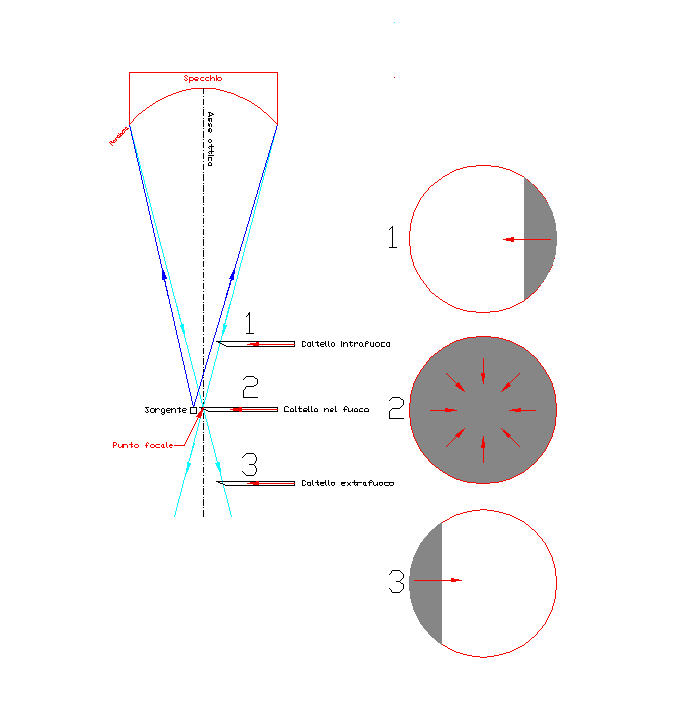
The principle is to ask yourself with eyes near the center of curvature of the spherical mirror (see picture), in front of the center of the mirror placed on a support with the optical reflection on horizontal axis, and point toward its center mirror a point light source (see note*) also placed in front of the mirror at about the center, and on the left side observer's eye.
(*Note DIMENSIONS OF OPTIMUM pinhole, OR MORE’ CONVENIENT SLIT: For good practical result of the Foucault test, Jean Texereau, to page 60 of his book “La construction du telescope d'amateur”, suggests that the diameter of the pinhole, or the width of the slit, They are included among the 20 and 50 microns.
Recalling that (for example) in a camera, the closure of the aperture increases the depth of field and sharpness of the image, but it reduces the amount of light and requires a longer exposure time; It follows that with regard to a pin hole or a slit, We have the same benefits.
A smaller width of the slit or the pinhole, would certainly increase the test sensitivity up to a maximum, achievable when it was corresponding to the diameter of the diffraction ring of the mirror under construction.
But such a narrow slit (or a pinhole so small), however, generate a great deal of annoying diffraction fringes that would make it much more difficult to evaluate shadows (but try to use a web-cam to watch the evolution of the shadows on a monitor).
In reality, a point source, or diameter pinhole 10 or vice versa 20 microns, It would not have the light intensity sufficient to perform the test well, and then it uses in its stead a vertical slit, which having width equal to the desired pin hole diameter (cioè from the 20 and 50 microns) but it is extended in height to about 4 or 5 mm, provides the same diffrattory features as of pinhole, but it is much brighter and much easier to build (… approaching two blades interposed with a piece of thin magnetic tape compact cassette that functions as a spacer, that should be removed when the two blades are secured in place with double-sided tape).
End of the note on the size of the slit or pinhole).
The observer will seek to move the source to his eye until you will see the fully lighted mirror. What happens when the eye distance and the source is close to the central area of the mirror radius of curvature (radius of curvature that is twice the focal length).
THE CONE OF LIGHT REFLECTED
In that configuration it generates a LIGHT CONE (light blue lines in the drawing) that the curvature of the mirror surface is reflected towards the observer.
The cone that has as its base the diameter of the mirror, has as a vertex the center of curvature, i.e. the point on 'optical axis that starts from the center of the mirror, where all the rays converge and intersect.
BEYOND however, observe that the point of the center of curvature, the sides of the cone of light continue towards the cross-operator, we see that the rays of light coming from the left side of the cone, which continue their stroke on the right side, and vice versa the roghts rays continue on the left side.
THE SHADOWS PRODUCED BY A KNIFE EDGE INTRODUCED IN THE CONE:
If now the observer, seeing the fully lighted mirror, introduces a vertical blade knife edge in the reflected light, with movement from right to left * (see technical note below), You can see the shadow of the blade in three different ways, depending on whether it has been introduced before the center cutvatura (in place “intrafocale” 1 in the image) ; or beyond the center (in extrafocal position 3 in the image); or in the exact center (position 2 in the upper image).
POSITION “INTRAFOCUS”
Assuming that the observer sees the blade as in the image 1 coming from right to left (that is, in agrement to its introduction in the light cone), looking at the image will understand that the right origin of the knife edge shadow is given by longer intercept the rays on the right side of the cone. What happens only in position before the center of curvature.
POSITION “EXTRAFOCUS”
Assuming now that the observer sees the blade as the disc 3 in the upper image, coming from the opposite direction, cuie from left to right, looking at the image we will realize that the blade knife edge (that is ever physically moving on your right) shows the shadow when it intercepts the rays after they are crossed in the center of curvature. So when you are in position “extrafocale”.
POSITION IN BENDING CENTER
When instead the operator introduce the blade in the exact position of the center of curvature, it would see the reflective surface darkening in a gray and uniform colour called "flat grey" like in the disc 2 in the upper image, without being able to appreciate if the progression of the shadow is from right to left, or vice versa, but it would see the entire area darken quite differently, as a result of the closure of a circular diaphragm.
At this point it becomes clear to understand how this method allowed FOUCAULT to find the location of the exact center of curvature of any curve simply feeling the introduction of the blade more or less forward on the optical axis of the mirror in question.
(TECHNICAL NOTE*: In building the simple tester to run the Foucault test, It is not mandatory but it is advisable to take the 2 following rules “STANDARD” general uniformity:
- Movement from right to the left of the blade perpendicular to the optical axis, for its introduction into the cone of light reflected by the mirror.
- Mounting the micrometer “Verniero positive” (that is, so that the BACKWARD MOUVEMENT corresponds an increase of longitudinal displacements measurement readings back and forth on the optical axis of the mirror test, denominated in technical jargon “DRAW”).
END OF NOTE).
THE MEASUREMENT OF CURVATURE RADIUS ON THE PARABOLIC SURFACE
not being possible to measure in a single time a curve having radius continuously variable, It is clear that we must overcome this obstacle by breaking down so in a series of circular crowns mirror dummy called "ZONE", each not very extensive, so that we can assume that within which, the radius of curvature changes negligibly, and therefore it can be considered “common”, finding the "flat grey" focus position.
Position that, as we have said,, is always reachable by moving properly back or forward the chariot of the Foucault tester that carry the knife edge (depending on whether the shadow is seen coming, respectively from the left or from right), and noting the readings of "DRAWS", ie of millimeters of longitudinal displacement of the tester chariot along the optical axis of the mirror (with the precision of a tenth of mm or better than the hundredth) corresponding to the position of the center of curvature of each zone.
Drawdowns that undergo appropriate calculations that we will see in a next article of example of manufacturing a mirror 200F6, They provide the amount of aberration and the correct positions in which to obtain a perfect optical.
(The term aberration means in practice the error that must be corrected, but which is now present on our curve under consideration, compared to the theoretical curve of a parabola taken as reference constructive).
We will then proceed to make a Couder mask (see specific and separate article in this same blog) with carboard, with a number of windows coinciding with the annuli to be measured. This mask will be placed in front of the mirror that lay placed on a stand with reflective surface in vertical.
we then installs the Foucault meter (the type of that shown in the article entitled “setup del test in Foucault "), Tester which must be perfectly aligned on the optical axis of the mirror, at a distance as close as possible to the length of the radius of curvature that is expected to have the mirror.
Then it will search the center of curvature of each zone, starting from the central zone, noting its longitudinal read measure. And as looking for the gray flat colour shadow (alias the center of curvature) within each pair of windows that identify each circular crown of the mirror, writing down the draw relative distance from the previous zone.
CAUTION because the central zone is a very delicate and important point of the work: It is the place of departure which will refer all of the following measures from ZONE to ZONE, and is therefore the most important zone because wrongs it, we carry the error on all other zones.
Everything this, and the followings, makes the central zone the more difficult to find with certainty the flat grey colour shadow.
The difficulty arises from the fact that the central area is the largest but it is also the least deformed, and thus it entails that it is necessary to move the carriage longitudinally along the optical axis of the tester of a greater amount compared to all the other areas that will be examined, but the serious is that in such a large displacement always seems that the shadow visible changes little or nothing (and this is due to the little deformation in that zone), making it almost impossible to be sure of the real “flat grey colour” reached.
Every operator who runs into that uncertainty creates its own rules to find the exact curvature center of the central zone. My rule is as follows:
– Move the carriage of the tester in an zone frankly intrafocus position, and introduce the knife (turning its adjustment screw) in such a way that the shadow on knife edge reaches the center of the mirror (i.e dark from right to the center), and note the longitudinal draft of that starting point.
– Leave the blade in that position and recoil backward with the cart until it makes visible the blade's shadow mirror exactly specular with respect to the starting point (i.e dark from left to the center)..
Basically when moving the cart you will see the progression of the shadow to the left, coming first to darken the whole mirror; which will last for a few mm of continuous going backward, and then the shadow will begin to lighten the right side of the mirror up to show the position of the mirror specular with respect to the departure. Location where you must stop.
Note the draw of that point of arrival.
To difference of the two readings of the draft values, is the distance traveled with the truck tester. Divide it then for two to find the center line and move the carriage to that middle position.
If everything went smoothly (and if the tester was perfectly with the axis of the mirror optical axis), that is the most likely location is the center of curvature of the central zone.
The test series starts from that zone in the Centre of the mirror and, procedento to evaluate each pair of windows of the mask Couder, come to the edge zone. Then you run a new series of measures descending from the egde to the zone toward the center.
You will then have two draft values for each measured zone, and these values will be averaged, the value of which will be used in the quality of the parable of assessment calculations.
At this point must be considered that the Foucault test, like all other optical tests executable by amateur (namely without sophisticated/or complicated hardware) affected by possible errors SUBJECTIVE of gravity inversely proportional to the experience of the performer.
The only safe reduction of that type of errors is then the use of MEDIATED values of a good number of measures. More are measures, and more their average value is representative the true real values.
All that said, , Is’ VERY GOOD THING, ADVISABLE SPECIES TO NEOPHYTES, that where performed more new sessions of measurements in "round-trip", in order to have at least four values (two “word” and two in “downhill”), on which to calculate an average that will correct already very quell'eventuale subjective error.
(everyone in “his heart” He knows his skill, and it behaves accordingly responsibly).
THE SENSITIVITY OF FOUCAULT TEST
is very, really very high, as a simple tester built in a traditional way with a few scraps of wood, It is historically considered capable of amplifying an optical defect of a factor of six hundred thousand. Therefore, in measurements of parabolas can be performed on the glass manual corrections such as to bring the value of the error-called "peak/Valley", a lot less than the minimum "entry" quality “entry level” , constituted by the value of 68.75 nanometers high. (ie millionths of a millimeter) which is an eighth the wavelength of the green light to which the human eye is more sensitive, above the error which an optical defect is visible would show.
Recalling that an error on the glass of the Lambda / 8 afflicts doubly reflected wave, a first time in incidence, and a second in emersion, The reflected wave generating a total error of (1/8+1/8)=1/4 Lambda, which expresses itself notoriously as Lambda/4 that is considerable entry level of diffraction limited optiscs, and it is believed that the input level of a good quality considerable limited only by diffraction.
Follow this one, another article that contains a complete example of the processing of a mirror 200F6 with the complete sequence of the ten test sessions of Foucault and offsets that were needed to bring the value of the initial quality of lambda / 1.3 to the value of the final quality of lambda / 10.4 . At a value that is much better than lambda / 4 value that represents the aforementioned "minimum wage" of barely passable quality for a reflective optical.