NOTEfor those who are going to read this article having already read the two articles before 1) “FOUCAULT TEST; what is it and how to function” e2) “Setup del test in Foucault”, it will be interesting to find an answer to the question that arises spontaneously, which is: “But when you have to start running the Foucault tests”?
The answer is that we make the first "orientative" test with Foucault,, without using the Couder mask, , when we have reached the end of polishing, , and all the craters left by the last abrasive grain have disappeared, , and we run::
until ) to take cognizance of the real form of pseudo-sphere that is automatically generated with the use of a full-diameter tool, which it has the intrinsic merit of regularizes the entire surface using the same time the application of the races(“Strokes”) having max overhang of 1/3 D “C. o. c.” (Center to Center) respecting also the lateral swiveling out of 1 / 6D.
b) b) Or to become aware of the shape genered by other sub-diameter tools,, however, discouraged for the impossible regularization of the entire surface that with those we can obtain,, seen the very very little (we talk about nanometers) tolerances “pic/valley”in play, and that they often oblige to regularize that surface with a diameter tool as close as possible to the diameter of the mirror.
(NOTE: The tools sub diameter are, however, required to achieve focal mirrors equal to or lower than F4, as they have a very pronounced concave dish that is impossible to generate full-diameter tools: So a beginner must avoid claim to achieve a mirror F4 or less as his work before, because the total lack of experience producing the highest probability of failing to deal with them).
At the end of polishing it is in fact interesting to verify what type of both the deformation of the surface of our current mirror, which may be of a perfect sphere, or have a start of parabolic shape, or yet to be already too deformed beyond the parabolic shape to a hyperbola.
Recalling that the deformation (aberration) the surface is calculated using the relationship hm ^ 2 / R
Where hm ^ 2 is the square of “average height” of the “window” on the mirror area examined, divided by the radius of curvature that is twice the focal length of the mirror.
We calculate those values for the center and the edge of the theoretical parabola taken as a reference for our machining, and subtract from the value of the edge to the center, obtaining a “draft” which represents the overall deformation value-edge center of the perfect parabola.
Foucault then perform the test on the center and on the edge of our mirror and also subtract the main draw to the edge, obtaining a certain numerical value.
If this value is Zero, is a sign that our mirror currently has a perfect spherical surface (the ball has a single radius of curvature and therefore is not deformed).
If instead this value proves between zero and the theoretical value of the difference calculated on the reference parabola. Then it is the most common case, because we'd already begun in the presence of a parable.
If this value proves greater than the calculated theoretical, then it would have already exceeded the parabolic shape to a hyperbola (defect that is obtained when it is polished with too long runs and / or too ooze left right).
A hyperbola is impossible to correct by making regress in the form of a parabola, why in our work we can just remove the glass, whereas in this case we would have already removed too, and you can not add. Then you have to go towards the ball again and always working with the tool at full diameter, applying the usual racing 1/3 c.o.c.; but this time taking care not to exceed overflows forward-backward 1/3 c.o.c. and side and those in the right-left direction of 1 / 6D.
In this way you cancel the error and returns towards the ball; ie towards a deformation of the surface that is lower than that which should derive impressing in our mirror the perfect reference parable.
End of NOTE.
—————————————
This article deals with the technical skills to Foucault's test, prelude to other future articles that will document the practice sequence of ten sessions that test, with correction decisions from time to time applied according to the test results, for the realization of a mirror 200F6, bringing it gradually to the improvement of its surface to the end with a lambda / 10.4 final error.
It is therefore necessary to refresh some preliminary notions.
WHAT 'NOTCH DIFFRACTION OR AIRY DISK
We know that the diffractive phenomenon is a characteristic of the wave shape of the light energy, from whose meeting of two wavelengths “in phase” from loro (or two wavelengths both “increasing”), It derives an extreme positive which produces a sum of light or incremeno; whereas, conversely, the encounter of two wavelengths in phase opposition (or an increasing and a decreasing) It can derive the opposite extreme of the dark negative, for mutual annihilation of the two waves. Obviously between the extreme light and extreme darkness are present all progressive intermediate gradations according to the possessed of phase components.
The wavelike behavior of light causes a source point high-magnification view with an optical instrument (including the eye, it is obliged to see it blurry because it is too close), You will not be seen as a simple bright dot but it will perceive a diffraction pattern (see figure below) formed by a central point that contains the 84% of the light, surrounded by a dark ring and a first clearer outer ring containing the 7% , then by a further dark ring and a second ring still clear outermost containing the 3% , and so on along with several other less obvious rings.
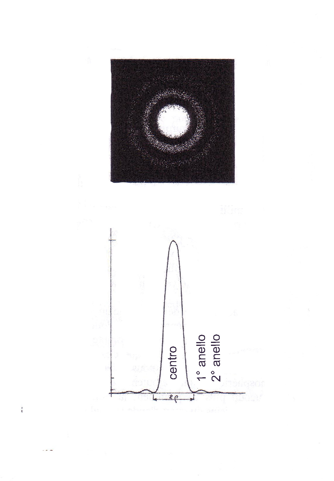
Figure 1
The radius of the diffraction notch is used in the Foucault test calculations and applies:
![]()
Where is lambda 0.56 microns, wavelength of yellow-green light which the human eye is more sensitive, and F / D is the focal ratio of the instrument.
Any optical defect of the instrument contributes to the rings to transfer a part of the central point brightness, which intuitively, enlarging the central point in a more diffuse spot, and less light, It goes to decrease the magnitude observable limit, and with it the efficiency of the instrument.
MAIN CRITERIA OF QUALITY '
to be observed in the optical workings are two, and they are pursued precisely in the execution of the Foucault test. They are: The criterion of Lord Rayleigh, and the criterion of Couder .
CRITERIO DI LORD RAYLEIGH
It concerns the perspective of resolving power (also said separator), and establishes that two diffraction images of its stars nearby, They are perceptible as separate, as long as the distance between them does not fall below the Airy beam (Half diffraction notch), provided that the maximum imperfection of the mirror, measured downstream from reflected wave peak, is equal to or less than one quarter of the wavelength of 550 (or 560 in some texts) already mentioned above.
That fourth wave is expressed by the term "lambda quarters" or lambda / 4
ITS EFFECTS ON PROCESSING mirror glass are that the latter must be worked with a double-precision, since un'onda reflected by an optical surface containing an error on the glass, It is damaged twice: A first time impinging on the reflective surface, and a second time emergendovi. That's double the damage determines that error up on the wave of a quarter wave length, on the glass should be halved to lambda eighths, why 1/8+1/8=1/4.
Just to know 1/8*550 nanometer is equal to 68.75 nanometers high.. And these 68.75 millionths of a millimeter tolerance thus represent "minimum trade union" to consider a perspective barely acceptable.
CRITERIA Couder
It safeguards the complete formation of the diffraction notch, and it establishes that, so that it can have all the features of the canonical form, all the light rays reflected by the entire surface of a parabolic mirror, They must reach the fire passing inside the circle of its diffraction notch, which it has a radius equal to that of the instrument resolving power, and it is calculated using the formula already seen in connection with the diffraction notch:
So by applying the formula to the 200F6 mirror of which we will follow the processing, it will have a will have a radius equal to diffraction notch:
r = (1.22*0.56)/6 = 4.1 microns
In other words, the criterion of Couder vigil in that the diffraction notch is not damaged by the absence of the contribution to its formation by any of the mirror areas that reflect you out.
The criterion Couder, although concerning the formation of the diffraction notch, It does not concern the distribution of light energy in it rings, whose possible dispersion is responsible for the loss of contrast of the images provided by the instrument. There is in this respect the criterion Francon that expresses an upper limit of excellence, which it is very difficult to achieve in practice, and that it is not essential to respect amateurly.
Francon establishes that perspective to Lambda / 4 is already affected by a fall of efficiency 62%, where instead one lambda / 16 instrument would have an efficiency of 92% beyond which should go because it would have ceased to notice any improvement, and optics is to be considered perfect.
Without the qualitative technical prerequisites, we find ourselves with
MIRROR READY TO PARABOLIZZAZIONE
Imagine then a fade in on a Ø200F6 mirror ready to parabolizzazione, therefore it has already suffered at least a number of hours of work, with the operations of:
- Roughing of the initial curve tending to the sphere with abrasive C60 with the arrow reaching dug (depth at the center compared to the edge) of 2.084mm, necessary to obtain the focal 1200 desired.
- Running-in "marriage" of the curves tending to the sphere, convex tool, and concave mirror. Until the perfect uniformity denounced by the absence of air bubbles between the two curves superimposed wet.
- Puddling of the spherical surfaces with abrasive grits gradually halved in size of the grain: Starting for example from the grain 180 (with beans from 50 microns) - then 320 (30 microns) – 500 (20 microns) – 800 (13 microns); whose exchange has occurred as that in a microscopic examination, the craters of the new finer grain, ALL had replaced the more coarse grained generated by the previous.
- Polishing with tool coated with pitch quadretti, and fine abrasive type Cerium Oxide or Zirconium refined (grain size ~ l micron) until disappearance of each spurious reflection of the sun incident on the mirror surface, whose light must pass in it without emitting any reflection in the point of incidence, how to pass the water surface stops, par excellence devoid of roughness down to the molecular level.
At this point our 200F6 mirror will have a pseudo-spherical surface, with a radius of curvature of 2400mm, which involves a focal length of 1200mm, quality glossy, transparent and suitable to be parabolizzata, ie parabolic yield, or flared towards the edge of a total value of 0.9 microns (0.0009mm).
PARABOLIZZAZIONE THE SURFACE OF A BALL
It tackles typically effecting the tool runs in the form of W insistent more or less on the center or on the periphery of the mirror,depending on the performance of Foucault test, remembering that the three rules of the universal game for glass scratching also apply in parabolizzazione regime and are.
1) Obtain the parable deepening the center of the ball. Putting the tool on the bench and maneuvering the mirror. It deepens the center. The operation, however, involves the removal of a large amount of glass and in principle is not convenient.
2) Obtain the flaring parable only the edge. putting the mirror on the desk, and maneuvering the tool works primarily the edge. The operation involves the removal of an average amount of glass.
3) Obtain the dish alternating the two previous modes.
The latter is the most efficient way, allowing to remove the minimum glass for working the edge and the center, respectively, starting from 70% the diameter of the mirror, and being that diameter 70% imposed as a reference point belonging to the reference parabola, the glass removal for the correction will be smaller and more convenient.
In the course of processing, however,, sometimes committing some wrong retouching, It can become worthwhile continuing for some distance work with one of the other two methods.
INSTALLATION OF EDDY TEST
For those who have not yet done, you should read in this same blog articles “FOUCAULT TEST; what is it and how it works” e “Setup del test in Foucault” , with images that can help you remember the following:
The Foucault test is preferable that they are practiced in premises without temperature fluctuations, such as basements or cellars, because such overhangs correspond dimensional variations of the mirror in question, who they are able to distort the measurements that are performed. Do not forget that the tolerances are measured in nanometers, ie millionths of a millimeter, which correspond more or less to the values that would cause the thermal expansion in the normal glass, and a little less in Pyrex.
It then places the mirror on its vertical support for the test, place at twice the focal length by Foucault tester, which it is therefore in the center of curvature of the sphere imprinted in the mirror.
Once the mirror leaning, especially if you have just finished its processing and if they have not been used of the thermally insulating gloves in its handling, it is left to rest and acclimate for several hours. This need is due to the fact that in both cases the mirror will be too hot, for the same reason already mentioned of thermal expansion.
Usually we place the mirror at the end of evening work, and measure it the next day. A few hours instead it is sufficient if the mirror is in Borosilicate Pyrex.
(Note that, an hour after handling the mirror, Foucault tester still shows the pseudo thermography turbulent hands in places where took place the grip without gloves)
For the correctness of the measures, you must perform the following two fundamental alignments between testers and mirror. The first of which provides that both the centreline of the blade of the tester that the slit of the light source should be at a height from the ground equal to the mirror center; and that the carriage of the tester should slide parallel to the axis of the mirror optical.
On then the LED light source, the light emitted by the oriented slit in the mirror and reflected back from it, It will have to be traced in the environment and flow in the space that is between the source and the blade, will be positioned where the operator's eye (the una your webcam).
NOTE: The installation of a webcam and the observation of shadows on a monitor is more convenient because the phenomena of diffraction of light that are formed at the edge of the blade and on the edges of the windows are eliminated with the appearance of vertical fringes that disturb the perception of spot color.
It would also be interesting to try another method, which in the 90s was using a camera, and that today could benefit from a webcam, It is proposed in 1994 by Ken Ramsey on US magazine Sky and Telescope, where the Couder mask was placed on the mirror but not directly on the TV monitor screen.
In tal modo, the large number of zones and their windows needed when working a large diameter mirror, They can be observed up close with a great advantage and convenience.
Returning to the alignment of the source, this is done by temporarily removing the slit from its seat in front of the light source, so that the spot is well brighter than it, and easier to track. Then slewing a white cardboard sheet in the area behind the tester to find out where the spot. And finally, slowly it orients the mirror or the spring support so as to bring the spot at the position useful, finally putting in place the slit.
After completing these alignments, they must be maintained throughout the measurement session, given that the measures are related and linked, if unfortunately some element also moved very little, should re-alignment and measures again.
After the acclimatization time of the mirror you can start the test session.
TECHNICAL DETAIL sTAnDArDIzATIon METER
For widespread constructive Convention, The meter will enter the blade always reflected from right to left. The light source (in this type of tester which has the sorgene independent from the movement of the blade), You will always be on the left of the blade. While the drawdowns on the micrometer readings of longitudinal adjustment of the carriage of the tester, increase with increasing distance of the mirror blade (situation called “Verniero positive”). Otherwise the “verniero” It will be negative and the measures will be marked with a minus sign. Anyhow, the data processing softwares require which type of vernier possesses the tester used.
THE TEST OF FOUCAULT and its basic principle
It consists in finding the focal point (…more precisely, the center of curvature which corresponds to the fire) of each zone in which the mirror is notionally divided by the mask which will be described shortly, through the displacement of the longitudinal carriage of the tester, and the shadow detection in "spot" that is encountered in the center of curvature, produced by the blade installed on the carriage.
Lama that the operator leads to intercept the cone of light of the reflected source, determining the appearance of a shadow visible from its observation point.
this shadow, according to the basic principle on which is based the whole test, (see figure below):
- It is seen to come from the right (or concordant to the movement of the blade) if the blade enters the reflection before the fire (position intrafocale) Position 1 in figure 3,
- or it is seen coming from the left (or in the opposite direction to the movement of the blade) when the blade enters the reflection over the focal point, in which the rays of reflection intersect . (position 3 in Figure 3)
- finally, (position 2 in figure 3) when the blade enters the reflection at the exact point of focus, shadow darkens the vision in a so-called "plain flat", as a result of the closure of a circular diaphragm. In other words, darkens the area is reflected without the operator can say that it comes from the right or left.
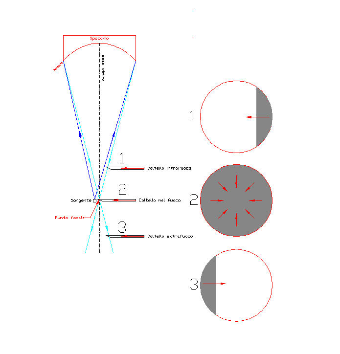
Figure 3
The operator's aim is to find the point away from the mirror such as to obtain for each area under examination, the spot color indicating the focal point of each area, recording the value of the "draft", or of the relative displacement of the carriage between the different zones constituting the parabolic curve..
THE MASK OF Couder
(See the article entitled "Closedthe mask couder: The thing, the reason why, when and how”).
Already it made as described in the article just recommended, It will present seven windows that compete with 4 areas that we will examine (Three circular crowns with two windows each,, plus a central disc), and will be ready to be installed in front of the mirror.
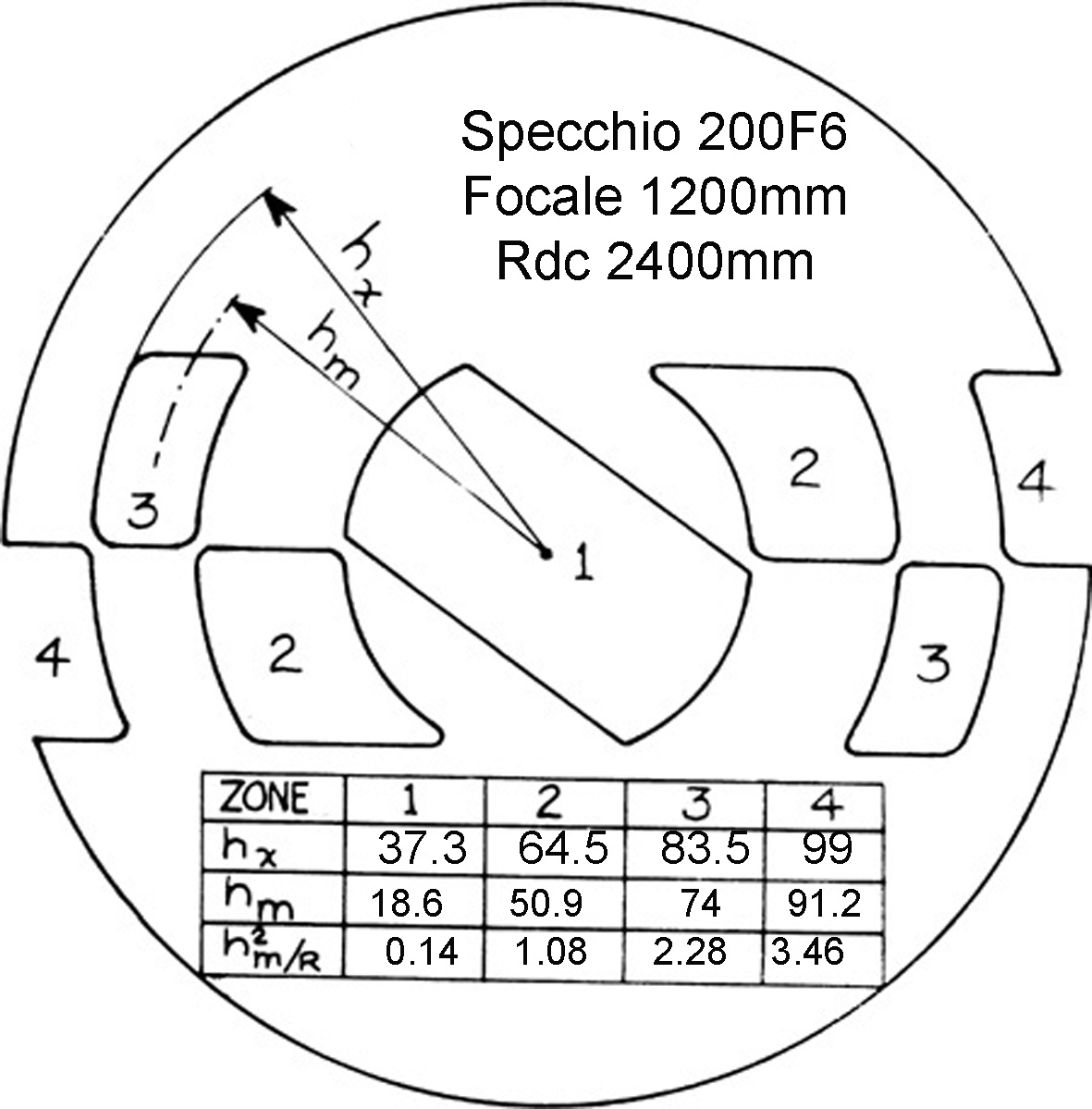
Figure 4
We will write the multiplication table on the mask with the data of each of the indicated 4 areas in which it is divided:
- The four values hx indicate the distance from the center of the mirror 'extreme outside of each window.
- The four values hm indicate the average height of the window, understood as distance from the center of the mirror, the center of the circular crown which constitutes each zone (Figure arrow hm It indicates the centerline of the area 3).
- While the values of hm2/R They are longitudinal aberration values of the parabola with respect to the sphere, and are the values for which to strive in mm.
In other words, these values indicate for that zone, the number of millimeters of “draft” the perfect parable of the center of the window of each of our mask area. The values hm2/R They will be compared with our measurements, and the results will be used to identify what type of corrective action to take, on the road of other progressive corrections and criteria, that will lead us to finish the mirror with the best optical quality possible.
The multiplication table on the mask in the ricopieremo also notes block , or "notebook of scratcher", we will use to perform calculations by hand .... Of course only in order to know how to manually derive the same data that we'll see processed by computer with a suitable spreadsheet, or XP with the program Figures, or other programs for the Foucault test scores. The knowledge of the manual calculation is not essential, but often it needs to take a useful shortcut, which are denied to those who do not know how to recognize.
TOLERANCE OF MANUFACTURE OF THE MIRROR
They determine its quality, and they are determined in particular by the criteria set out above, but also by the deviation of the values detected in the measurements of the drawings of the zones, compared to drawdowns of the theoretical perfect parabola, and recent deviations should aim at zero so that the highest quality, it is only a matter of time. But that, precisely because it is a matter of time, often does satisfy the amateur astronomer “scratcher of glasses” of a value not excelled, but that will certainly be a lot better than any commercial telescope mirror.
SENSITIVITY 'TEST OF EDDY
The Foucault test is able to amplify about 600 thousand times the surface defects making them visible and quantified, although those of infinitesimal dimensions.
PRACTICAL IMPORTANCE OF TRAINING TO FOUCAULT TEST
The ingeniously simple operating principle of the Foucault test, founded on the only rule of the three cases of origin of the shadows, (Right in intrafocale, from left extrafocal and all 360 degrees angle around the spot color), It produces on a perfectly spherical surface, shadows of identical intensity over the entire area of the mirror as the blade proceeds to cut the cone of light reflected.
In practice, the shadow will be homogeneous and almost identical or slightly more nuanced than that drawn in number discs 1, 2 e 3 of figure 3.
But things get complicated in practice, with the fact that the mirror is generally no longer a perfect sphere, but already it has areas with slightly different radius in the way of parable. And then the shade provided is no longer homogeneous as in the sphere, but it shows the minimum change in the curvature of the reflective surface radius, the reliefs as lighter areas that fade in the cavities as darker areas, who may in turn fade in subsequent clearer reliefs and so on.
For that reason, the installation of the couder mask is of paramount help to be able to perfectly define the specific pair of windows on which to focus its attention. (Besides the centrale zone, that if the mirror is not drilled has a single window).
There remains, however, the difficulty of the neophyte to focus in seeking the simultaneous and identical colored flat on two diametrical windows of his interest, in the presence of various disorders data from the light and dark of the adjacent windows, and the diffraction fringes produced by a good cleavage by 10 microns.
Here it is essential that each one teach well to juggle in the mirror of their shadows, taking advantage of the first sessions of parabolizzazione for testing, and permanendovi acquired up to greater safety.
On the Foucault test and the progression of the shadows behind a mask Couder, Today there are a number of texts on the net, images and sample movies that can possibly come in handy, or confusing. The own experimentation, having in mind the three origins of shadows, It is all you need, and still it remains the best way to become proficient.
and we are ready to perform the testwhich we will see the practical use of the findings of the drawings of each zone, starting with an assessment only performed manually, and then continue with other “IT”.