As we have seen in this article, a convex secondary mirror can not be tested directly in general (*) . One of the methods is used to refer to a concave mirror which has the same shape of the surface that we want to get on the convex mirror.
By overlaying the two mirrors, the analysis of the interference fringes by means of a interferometer Newton, highlight the differences between the two surfaces in question, that precisely the caliber and the convex mirror.
We know how to assess whether the space between the two surfaces is in its concave or convex time, in other words if the points of contact between the two glass panes are at the center or at the edge, and we also know how to quantify the difference between the two surfaces as a function of the number of Newton's rings.
Let us now analyze in detail any other indications that we can deduce from the analysis of interference fringes and to build an effective method for the correction of the surface up to the desired shape.
To do this we need to have our interferometer Newton and examine two glasses , with the premise that in this article will analyze the interference fringes pointing towards the side opposite to the “tilt”, that is to say that the greater thickness of the spacers interposed between the two panes will be in the edge closest to the observer. (1)
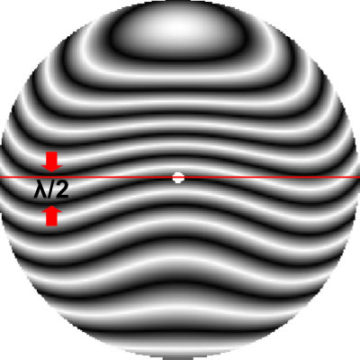
Fig. 1 – Fringes of interference
This simulated image, It represents two very close surfaces between them, but they still have a difference of about one-half wavelength .
Recall that the distance between two successive fringes is lambda / 2 and you can evaluate the maximum error of the surface under examination by drawing a diameter and simply counting the fringes ( dark ) that intersect the diameter.
READING SINGLE FRINGE
The meridian through the fringe to the center is the one that interests us most, therefore “isoliamola” from everything else and examine it independently of the others.
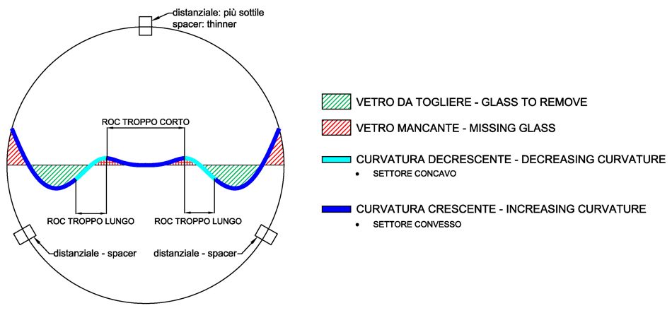
Fig. 1 – Analysis of single interference fringe
We are looking forward to better define the meaning of this scheme, bearing in mind that the trend of the fringes is a function of positioning of the thinnest spacer (1)
MERIDIAN FRINGE THROUGH THE CENTER
We arbitrarily chose this fringe, therefore all the directions that follow are based on the center of the mirror, but nothing prevents you to choose another fringe, the important thing is to have points of contact with the diameter, if we choose a fringe which intersects the diameter only at the edge, then all our considerations will be equivalent but referred to the edge of the mirror.
The reasons why it is preferable to use the loop fringe to the center are:
- In a system of two mirrors the entire optical design is based on the radii of curvature of the center, both the primary and the secondary, so keep an eye on the central part ( which it is the one closest to the sphere of origin ) without changing it too, working the remaining mirror, It needs to remain within tolerance limits their schema, an excessive change of the Central Secondary ROC significantly alters the design parameters, with the risk of being a minor not optimized for the design scheme.
- The center of the convex is a very delicate area, working it is “flattens” easily, It is the equivalent of the edge in the concave, a small error on the central part and will be forced to remove glass from the rest of the surface to correct.
However, there are cases where it is impossible to see through the fringe to the center. For example at the moment when all the mirror is convex with respect to the caliber. In this situation ( as we'll see ) we are forced to refer to the fringe to the edge and remove glass from the central part.
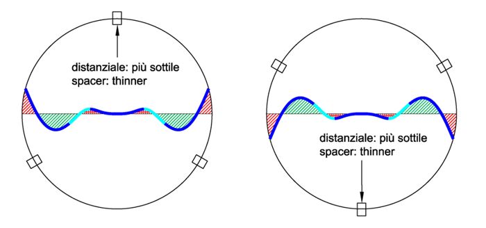
MISSING GLASS
Ideally we divide the mirror into two sectors, that beyond the diameter (compared to our point of observation ) and the previous. In part“North”, we will have plenty “glass missing”, namely that, respect to the gauge, would be added to comply with the sample surface:
A border or a retorted “this by” (with respect to the sample surface of the caliber ) always will come to be in this area. In other words, the convex surface in these areas is “lower” respect to the gauge.
GLASS TO REMOVE
Similarly, the whole area “South” than the diameter, It represents the glass part to be removed to comply with the sample surface. A raised edge or a “collinetta” They will always be confined to this area, and the fringe of the trajectory will be unequivocally confined in this area.
things can actually become more complicated, when for instance a raised edge or a hillock come to be in a part of the surface which is, as a whole, lower than the caliber, then we will have the same time that we have to remove and add to the glass surface, which it is obviously impossible, Therefore we will always refer to the largest part of the area that needs corrections and leave the small local defects the finishing touches.
BEND DOWN AND GROWING.
In the chart we can see how the zones “South” They are reachable by the fringe only if its curvature decreases or, if you prefer, if the mirror is in that area “flattens”. Similarly, to access the north, fringe will inevitably increase its curvature and thus become more “convex”.
In a convex mirror, removing small quantities of glass from a given area, We do nothing but increase the curvature of the inner adjacent areas and decrease that of the external adjacent, leaving almost unaltered the curvature in the intermediate part of the working field.
RADII OF CURVATURE
Closely associated with the previous deductions are the curvature of the various zones rays, which will be smaller or larger than the size range depending on whether you are in the northern or southern sector and the increasing or decreasing radius bend will be determined by the performance of the corresponding point.
CORRECTION METHODS
These cisuggeriscono results as it is possible to intervene on the secondary convex to build the final figure:
The whole processing of the secondary, It is reduced to achieve so also “coarse” a few fringes difference with the caliber , and then intervene with the finishing touches with extreme precision. Then it examines the central fringe and you work the more zones “that are high, namely, those which are within “South” the reference diameter, trying not to touch the areas that they are already lower than the caliber.
In theory from time to time should we build and use a tool whose extension is equal to the area to be machined. In practice we resort to other methods:
- a special set of circular ring-shaped tools which work exclusively some predetermined zones ( central, median and peripheral
- only one tool at sub small diameter that can effectively replace all other crown tools.
the first solution, faster in processing, simpler in the technical but less accurate, It is more suitable for the early stages, during the parabolizzazione away from the ball up to the achievement of only four or five rings ( in Newton ) of difference between the two surfaces. The second solution is slower and more difficult but will allow us to operate with greater precision during minor adjustments.
We will see in a future article devoted entirely to the construction of the secondary hyperbole ( with manual processing ) how to use these techniques, for now let us examine a particular case, the fringe of our sample and see how it is possible to level the convex mirror to gauge, that is, how do we make “starboard” the fringe without considering the merits of the techniques and their implementation.
EXAMPLES OF CORRECTION OF SURFACE WITH tool sets
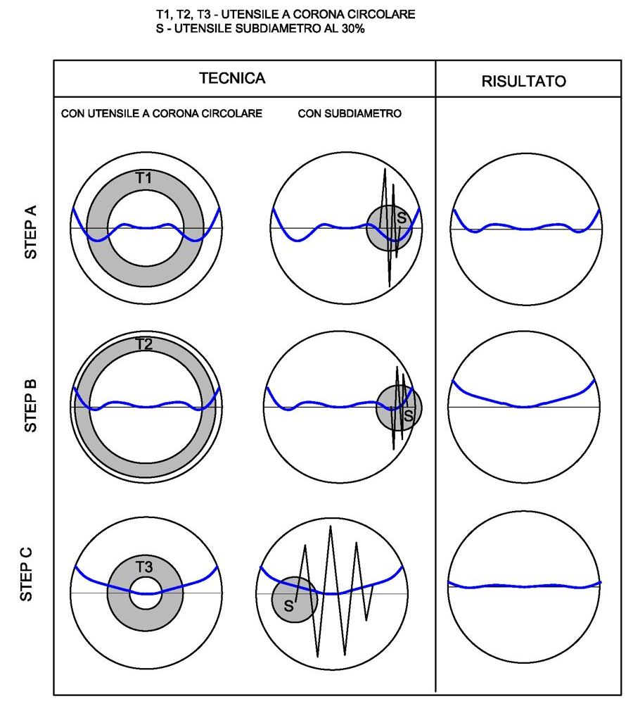
Fig. 3 – correction techniques to a convex mirror
STEP A
Suppose you have all the necessary tools , We start to work in the area that has the largest deformation in the area “glass to remove”, so in this case, the area between the 50% and the 60% ( circa) the diameter.
we can do it with a tool annulus, or with the sub-diameter, the result will be equivalent if the techniques are performed correctly ( as we'll see, the two types of tool must be used in a different way ).
After a few sessions will see the central part of the fringe shift to the northern zone. the difficulty lies in the fact that in general asporteremo almost the same amount of glass in the entire treated area, So we will make more “low” all the points within the region being machined.
The result would presumably be similar to the one in the picture.
STEP B
at this point it is not convenient to insist with the same area, because the central sector is too deepen respect to the edge , should move and work outside the periphery , lowering and harmonizing it with the central part.
STEP C
Now we find ourselves in the position that we mentioned before, in which all the mirror is convex with respect to the caliber and the fringe passing through the center is located in the area throughout “glass missing”. We will take at this point as the reference fringe that intersects the diameter at the rim, which will be almost similar to this central but shifted with respect thereto in the area “glass to remove” e, in accordance with our previous considerations, we will work and the central median of trying not to lower our current reference, ie the edge.
The final result should not be very different from that in Figure. At that point, we can repeat the sequence of operations , starting from (new) deformation that there seems to be the widest, in order to approach as much as possible to the theoretical straight fringe (**).