As mentioned in the preceding article (Hartmann test) in this post I describe the method which I have recently begun to be used to test the optical during processing and which is based on the Hartmann test.
In the mirror parabolizzazione phase, in particular the last stage of refinement of the shape of the surface is necessary to know with precision the error profile in order to intervene with effectiveness.
To rebuild this profile typically is used, at least at the amateur level, the Foucault test with Couder mask, but in my personal experience I was never able to optimally utilize.
The greatest difficulty I have always found in assessing what was the precise longitudinal position of the carriage to which the blade would generate the spot color in the two symmetric windows of the mask. In fact hardly I could determine this position with a margin of uncertainty between different measurements within 1-1,5 tenths of a millimeter, perhaps penalized by the distance from which I had to evaluate the hue (circa 4 m, ie the radius of curvature of the mirror), combined with the modest size of the windows necessary to have an adequate number of measuring points.
A sensitivity in sizes 1-2 tenths of a millimeter, however, is not sufficient to be able to define with precision the profile of the shape of the surface, especially in the edge region and especially when you begin to achieve high levels of lambda values.
For groped to improve the reading of the measures I have always thought that the best solution themselves to use a test that was the least subjective possible.
Among the tests that I have estimated that in the classic version of Hartmann gave me the inspiration for groped in this direction. This test involves placing a point light source in the center of curvature and an appropriately perforated mask in the vicinity of the mirror. The light reflected from the mirror passing through the holes of the mask returns towards the center of curvature in the form of small light beams that if intercepted by a photographic plate or by a digital acquisition device (devoid of the optical part) manifest as a series of light points. By analyzing the position of the luminous dots it may be able to determine the shape of the mirror surface.
There are many variations of this test but one I thought of using, because I thought it was the easiest to implement two photos, an outlet in intrafocale and a socket in extrafocal.
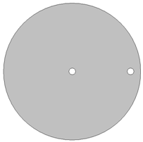
To give an idea of the operating principle of this test is enough to think of a mask to be placed in front of the mirror such as that made in the following figure, or with a hole in the center and one in a marginal position.
By positioning the webcam sensor intrafocale position you will get an image with the dot marginal window in a right-most position with respect to the central window dot, while positioning itself in extrafocal you will get an image in which the dot of the marginal window will be in a leftmost position with respect to the central window dot.
Evidently there is a position in which the two dots will be exactly superimposed and this position indicates the point at which the returning light axis of the cone from the marginal window intersects the optical axis of the mirror. This position you can easily find mathematically if you have access to the following data:
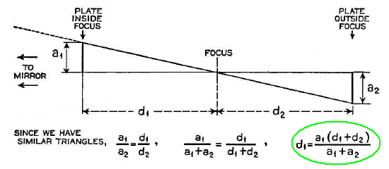
So it is necessary to know the distance in mm or marginal px between the bright spot and the bright central spot in the two pictures (a1 ed a2) and the longitudinal distance between the two photos (or the amount d1 + d2).
You can think of repeating this operation for a mask with several holes for each of which calculates the position of the beam of curvature and consequently the draw difference with respect to the first window starting from the center to obtain the same data that are obtained with the test of Foucault, ie draft values of the various zones and the average distance from the center of the windows of the mask.
If you are using a mask with holes arranged over the entire surface you will be able to analyze in a single shot the entire mirror. This test, however, and very sensitive to any misalignment between the point light source and the position in which you place the photo sensor, and less than not be able to create a set-up of the tester so that the two beams are coincident almost always notice the differences between the draft values of two spots symmetrical with respect to the center of the mirror (while it should be identical if the mirror was perfectly axisymmetric).
Another aspect to be considered to improve the accuracy of the measurements is to take pictures from suitably distant positions of the center of curvature of the mirror (and in any case outside the limits of the caustic), but this implies the need to have at the disposal of cameras or webcams with the size of very large sensor.
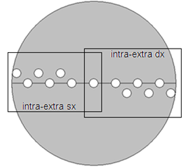
Taking into account these limitations I decided to perform the test with a mask with holes arranged only along a diameter of the mirror, or a little away from it, as shown in the following two figures, so that you can align with the greatest dimension of the webcam sensor:
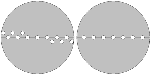
In this way, with the holes arranged so you can minimize the negative effect introduced by slight misalignment between the two outward and return beams or slight tilt of the camera sensor, going to mediate draft values of two symmetrical windows.
Since the webcam at my disposal had a limited size sensor I had to take two images for each position to be able to cover the entire area under the bright spot (making sure to always include the bright central spot in photos), muovendomi laterally with the carriage of the tester, getting around 4 series of images: Intra-right, intra-left, Extra-Extra-right and left.
Once obtained images will therefore be necessary to determine the center of each bright spot and calculate the distance of each of them with respect to the central spot. This operation can be done manually evaluating eye to the center of the spot, which is likely to introduce a dose of subjectivity to the test that was my intention from the beginning to avoid. For this reason I implemented a simple code in Visual Basic (because they are not able to find any dedicated software), to help me in this, which calculates the center of gravity among all bright pixels that make up each single spot. In addition to improving the quality of the final result I acquire at least thirty images for each position, that the special software shall analyze mediating all the individual results.
Once analyzed all the images the software automatically open an Excel spreadsheet preprocessed in which fits all the data necessary for determining the profile of the mirror surface.
Although the process seems laborious and long actually allows you to take the test and to reduce all in a short time, or in line with the time required to perform a single test Foucault, but with the advantage of having carried out a measure that is already the average of well 30 or more different images, and appears to be the less subjective possible.
In principle,, after aligning the tester with the light beam, the webcam mounted and connected to the PC (that is to say more or less the same time to set the tester for the Foucault test), They need a couple of minutes to acquire all the necessary photos and 4-5 minutes to reduce all data.
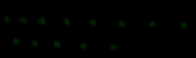
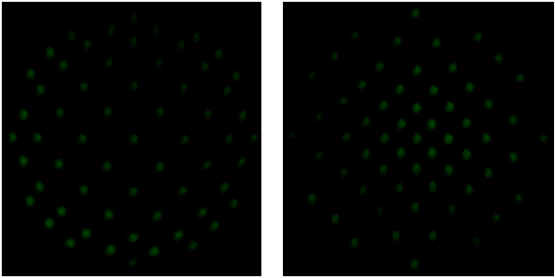
To give a practical example here are some examples of photos that I acquired during some tests:
As mentioned earlier due to the reduced size of the sensor at my disposal I had to acquire 2 images for each position to be able to cover all the luminous spots awfull laterally with the carriage of the tester.
right Intrafocale:
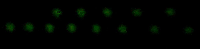
Intrafocale left:
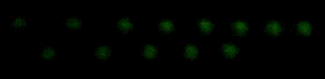
right extrafocal:
extrafocal left:
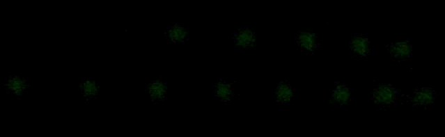
If I had access to a larger sensor, I could directly acquire two images such as these without having to laterally move the sensor to resume all the luminous spots:
Intrafocale:
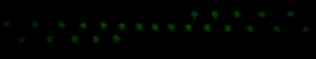
Extrafocale:
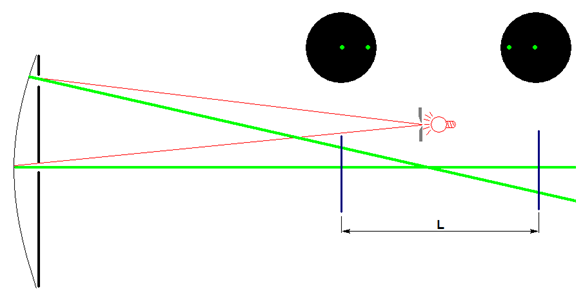
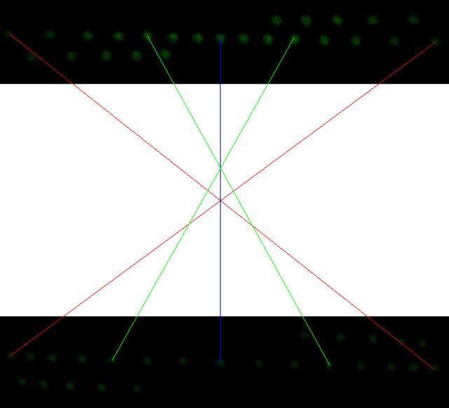
Again below the principle that takes advantage of this way of analyzing the mirror surface, using 2 real images that maybe will help you understand better than ever. The blue line that connects the center points of the two pictures is the mirror optical axis, while the red lines and green lines instead represent those which would have the paths of each bright spot going from its position in the respective position in intrafocale extrafocal. As you can see the green lines intersect at a different point from the red lines and this is due to the different mirror curvature radius under the different windows of the mask.
Comparing between them all the positions of the centers of curvature, They can calculate drawdowns of all zones by substantially reducing the data exactly as you would with the Foucault test.
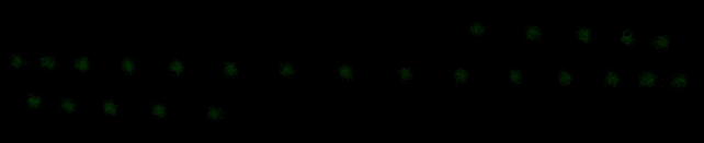
In the case of an even larger sensor I could acquire these type images that cover the entire surface of the mirror, as expected in the real Hartmann test.
Due to the small size of the sensor at my disposal, each of these I have been able to obtained only by gluing together 4 different images. Even with a modest sensor it is possible to intercept all the luminous points, just get closer to the center of curvature of the mirror, where the rays tend to converge more and more. The closer you get to the point of fire, however,, also the bright points are close to each other starting to merge together preventing the identification of well where one ends and where the other begins. For this it is necessary to adequately move away from the center of curvature of the mirror in such a way that the dots are sharper, isolated and distant as possible.
In the last session parabolizzazione I made I always used this method to test the mirror processing having no way to appreciate the quality. In addition I could use a mask 12 windows on the radius, unthinkable thing to do with the Foucault test and Couder mask, that otherwise would generate too small windows near the edge.
One of the qualities I intended to try and I have come to our attention during the various sessions of measurement was the verification of repeatability between successive measurements.
So here are some examples of these tests:
EXAMPLE 1:
In the following figures carry a passage of a processing plant where, after having carried out a measurement of the mirror profile, I decided to intervene in order to lower the central area of the mirror going to perform a short working session with sub-diameter tool with W rides within a circumference of 100 mm radius, and then perform another measurement. He not is went to work in areas with higher radius to 100 mm I expected that the shape of the surface in those areas did not change, and in fact it is very clear that there there is a very good correspondence between the values before and after processing.
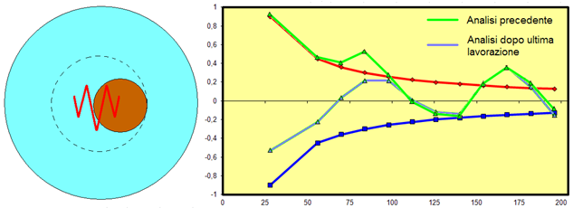
EXAMPLE 2:
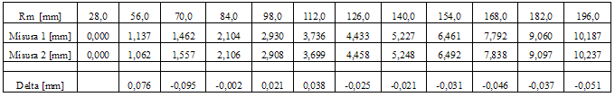
These however are the other values 2 test distance events in one day. It 'clear the correspondence between the values of the two sets of data that have a smaller maximum deviation of a tenth of a millimeter and averaged approximately half a tenth of a millimeter.
In conclusion, the feasibility of this test, at least at the amateur level, It is heavily influenced by being able to find the software that reduce the data quickly, otherwise the time for obtaining the results would become too long and quite laborious accounts do not make their use affordable.
To use this test I had to implement a small code in Visual Basic because the network was not able to find any that suited my case (P.S: I had no knowledge of programming when I started thinking about this type of testing, but with an old school book and a bit 'of time for the study I was able to implement something useful).
If anyone would like to try this type of test, and he needed this little program for data reduction can find it at the following link in the form of compressed files RAR. Besides the little program it is also a word file with instructions for use :
Hartmann test by Mirco
While it would be even more welcome if someone with skills in programming wishing to engage in 'process a little program (definitely best and most effective of my) that would be unique not only at national level.
For completeness of information it is possible to perform this test also through a single image taken arbitrarily or in intrafocale or extrafocal.
The principle, however, does not change as you can think of the mask itself (placed in front of the mirror) as one of two pictures needed. In this case, however,, for data reduction, It is necessary to know with precision the distance between the sensor and the mirror and the size in microns of the pixels of the sensor to be able to convert in mm the distance between the luminous spots (It is seen that the distance between the windows of the mask are usually expressed in mm).
The software for data reduction for this type of set-up meter is called Hart1d. Unfortunately, the link that I was able to find that refers to the page where it can be downloaded at the moment is no longer active, but searching on the net you might find anyway. If the link I will return to active post it again in the article.
LonRobie
LonRobie
Giulio TiberinI
arpafab
Bartolomei Mirco
Alberto Bugoloni
Bartolomei Mirco
Bartolomei Mirco
Alberto Bugoloni