SOLIDITY’ = INDISPENSABLE PREROGATIVE OF THE TRUSS TUBE
The need to have portability and compactness in Dobsonian telescopes (characterized by a frame ingeniously reduced to the essentials despite the large aperture of the primary mirror Newton) has meant that the optical tube of such instruments, must obviously having a larger diameter for just contents the big primary mirror, It could be replaced (for reasons of transportability and dimensions), give one “virtual pipe "in the shape of cylindrical trellis, generally composed of n. 8 simple aluminum tubes whose dimensions we speak more than in the specific chapter.
Truss for Dobson (Click on image to enlarge)


Obviously the strength of the optical real “monolithic tube” -, It had to be THE constructive PREROGATIVE indispensable to reproduce as such, in the characteristics of the truss, the arduous task of connecting, rigidly joined at the perfect optical axis, the two extreme optical parts of the telescope (that one of the two parts is the case of the primary mirror, which is below; and the otheri is secondary mirror and Focuser cage, who is at the top).
These parts connected to precise mutual distance should allow the focus with our ocular inserted into the focuser, without allowing flection that are diverting the components of the telescope from their membership on the optical axis of the instrument.
THE TECHNICAL SOLUTIONS COMING FROM THE LARGE SERIES PRODUCTION OF DOBSONIAN TELESCOPES
The market for large series telescopes Dobsonian type has accustomed us to construction types of good validity for new instruments, but poor in pasting times.
In first place, the use of chippings woods (though “melamine nobilited” or with others laminates) to build a very low cost effective structure of great series, It has several flaws, including a disproportionate weight against the simple but light and robust (it's more expensive) composite material made from plywood, that are ok even in simple poplar wood.
In addition, the particleboard, although melamine, is known to record by its very nature a significant absorption of moisture that (plus the fact that it is NOT a crossed-multilayer-laminated material, and so it is NOT as robust as a composite), go in time to encounter unwanted structure deformations which, if not addressed with appropriate extraordinary maintenance, reduce the maneuverability and the good use of the instrument.
That structure Dobson big series, It has the appearance of domestic furniture. But in contrast to the comfortable places where they spend their lives household furniture, the telscopio Dobsonian will live his life stationed in cold and damp places of observation, or it is kept in local evacuation with very different microclimate from the comfort which is subject “Lifetime” the normal household furniture.
In the second measure,, industrial economic needs of that kind of production that must contain costs, often favor, also in construction of the trellis optical tube, a constructive simplicity not always up to the required flexural stiffness characteristics.
This category includes the truss consist from only four straight poles, which in the inclination of the variable “virtual optical tube” implemented for the normal observation of astronomical objects that are located between the zenith and the horizon, not oppose the maximum inertia in the solicitation of increasing deflection with increasing inclination of the telescope, at less than on a remarkable structural oversizing, that means an increase of the weight of the telescope.
To make matters worse performance also contribute to the fixing of truss poles extremityes, when this, (again for reasons of "business economics"), are simply obtained by crushing the truss poles in form of flats ends.
In this case one obtains the notorious "crushed poles" that transform the high moment of inertia to bending of a metal tube, in the lowest bending moment of inertia of a flat. Losing with what, the benefit of the rigidity provided by the high moment of inertia of its tubular sections, for the construction of the Truss.
These two negative examples are very simple to be realized at very low cost. But in order to compete adequately with a counterpart trellis system "guyed", require a supra important mechanical design.
That over mechanical design (when implemented), affects the weight of the telescope, worsening the handling and its transportation to the observation sites.
Unfortunately this often over-sizing is not even implemented. So that kind of telescope, a fortiori, suffer of undesirables optical misalignment, that we detect by loose of collimation.
THE BEST TRUSS TYPE
The best technical solution for the stiffness of the frame is the form "counterwind" is at 6 or 8 pipes.
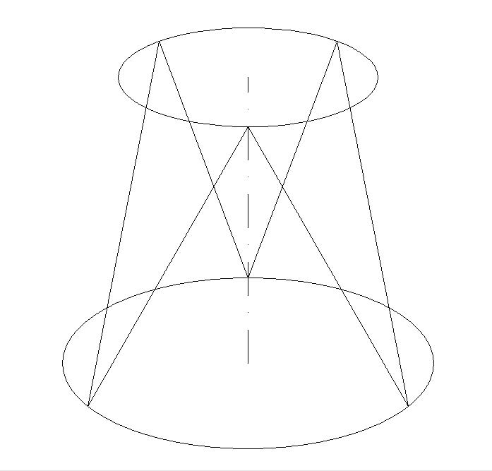
A truss to 6 pipes joins two circles with pairs of pipes fixed at a distance of 120°. Similarly, a truss to 8 pipes join the two circles with pairs of tubes set at a distance of 90°
The term "stay" (borrowed from marinaresco jargon), It means in mechanical an inclined rod which acts as a "brace". That is a tie-beam that reinforces a structure for the purpose of making it stiff and stabilize, compared to forces tend to bend in the opposite direction.
In guyed mast of a telescope, each tilted tube component, lying the perimeter of the frame , In addition to its own big inertia due to its round section, It also constitutes a tie-beam able to counteract the bending stress acting in the opposite direction on the other tubes.
Therefore the round section of the cylinder forming the structure of the Truss, in addition to simulate the telescope tube, becomes a whole strong mechanic, in which the bending stresses in any direction they be carried out, are neutralized by the tube-tie anchored in the opposite direction to that strength.
The only stress that this configuration would remain sensitive is the compression or traction along the central axis. But in a telescope we not have traction, and compression is given only by the small weight of fully equipped secondary cage.
THE TRUSS TUBE CLAMPS
Usually, and for constructional simplicity, the cases of primary mirrors of self-built dobson are cubic, while the coffers of the secondary mirror are cylindrical.
So the trellis connection is made between the circumference of which is at the base of the secondary case, and the square which constitutes the perimeter of the primary mirror case.
The circumference of the base of the secondary case lends itself to a simple truss tubes fixing, fixed in pairs. But for the primary square case, for simplicity, It is necessary to provide many terminals like are the truss tubes components.
There is still the possibility that the primary case either are as cylindrical as secondary cage.
In this case the connection of the trellis extremes are two circumferences, and you can then provide, both on the one and on the other circumference, fixing tubes in pairs.
Connecting the pipes to the two ends cases of the telescope, must be designed in such a way as to have the following characteristics, which are in fact determined by the quality of the truss tube clamps:
1) To provide guidance to the individual tubes according to their inclination, in order to facilitate the fast telescope assembly by one person.
2) Being simple type in order to facilitate the mounting operation which takes place almost always in the dark.
3) Possess adequate strength so as not to frustrate the intrinsic strength of the stayed truss (that is, as already said, avoid if possible the anchorages of the crushed tubes and reduced to strip).
The feature mentioned in paragraph. 1, the guide of the tubes according to their inclination, it is important for easier assembly, and it can be achieved in different ways:
-One of these ways is the fact that the individual tubes are inserted into oriented terminals and constructed with stretches of slightly larger diameter tube and therefore able to accommodate and guide the lower ends of the trestle.
the truss clamps that guide the tubes


The terminals are placed on the perimeter of the primary mirror case, fixed oriented and inclined so much of which serves to bring together the adjacent pairs of rods in the common point of attack at the base of the checkout of the secondary.
DESIGN CHANGES TO STREAMLINE THE ASSEMBLY OF THE FRAME
Another way to obtain the same unique orientation of the lattice tubes in phase the telescope mounting, consists of coupling the 8 tubes two by two in 4 groups, in an articulated manner to the upper end divaricabile.
Type of truss tubes pairs spreadables


The 8 trellis sections will then be transformed into 4 pairs of tubes joined at one end to form a letter V, by means of their fixing non-blocking to a piece of aluminum angular.
The attachment is made with non-blocking lock nuts closed without contant backlash, but in order to allow a "pasty" movement of the two tubes. This serves to manually vary the angle comprised in the letter V, to be able to open up to achieve the insertion of the fixing hole praticanto the lower end of each of the two tubes, on their relative bolt protruding from the primary case.
An undoubted advantage achievable with this system, It is that you do not need the more expensive (if purchased) 8 of the lower clamps of the pipes to the primary case, but they are sufficient n.8 simple bolts protruding from it.
But the movement “pasty” of the two tubes it is also used at the end of the evening of observation, in phase of the trellis disassembly, in order to close to zero the angle of each pair of tubes, for easy transport.
Another great advantage is provided by the above mentioned 4 angular segments that combine the 4 pairs of tubes of the trellis. In fact, they automatically provide a perfectly orthogonal to the optical axis of support base for the base circle of the secondary case, that there may be placed above and fixed at four protruding bolts from the four angular center.
Indeed, screwing its four fixing knobs, the base of the case of the secondary automatically oblige the truss rods to be arranged so as to present the supporting plane exactly perpendicular to the optical axis (unless of course coarse drilling errors for the installation of four bolts that secure the tubes of the trellis at the base of the primary case).
Flats of support to secondary case provided by pairs of lattice tubes


Certainly a further simplification of the method of the telescope mount “on the field” (however, a little complicating the construction of the pylon itself) It is to extend the principle of the union of the pipes in pairs, transforming the entire trellis in a single object collapsible to “accordion”, to open from time to time in the right width for installation, and reclose into a single beam at the end of observation.
In this case, for a variation of my telescope in case 250F5, I found it easy to replace the tubes of the trellis (that as per the following picture, They are of length 102 cm), with pairs of angle sections of long aluminum 54 cm, thus having the possibility (in case of necessity) to halve the length of transportable trellis completely disassembling, but though lengthening the telescope assembly time on the field.
Variant collapsible truss


USEFULNESS’ MAKING UNMISSABLES THE THREADED KNOBS
The anti-loss of the fastening screws (as well as avoid their fall on the primary) is an important convenience since the installation of the telescope is activity at night, on-site observation.
To be made best unmissables are blind female threaded knobs. In my case your provider and drill a through-hole diameter 1,5 mm at the center of the knob knob, that is in that position that coincides with the opposite threaded hole Center.
In that small hole I spend a nylon thread from "deep sea fishing" diameter 1 mm, (or by small brush cutter), after that, by means of a lighter, the bottom ends of the wire a a nylon ball barely larger than the hole 1,5 mm that prevents the slip off knob.
The other end of the line must then be attached to the telescope structure pinching it under the bolt head that you have to screwing the knob, or pinching it under his special screw.
The result is that the little nylon ball concentric to the bolt thread, leaves open the possibility of endless rotation of the knob, and we are housed extreme of a threaded hole, in turn originally practiced with a drill bit, It is also found in closed bolt, to occupy an empty conical cavity, that does not disturb in any way the mechanical connection and not ruin the nylon ball.
KNOBS
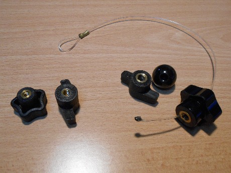
Types KNOB BLIND THREADED FEMALE. Pursuing a hole 1,5 mm at the center of the brass threaded sleeve, and inserting a thick thread from nylon fishing, by making the unmissable object by melting the end wire in a little ball (see knob to the right)
DIMENSIONING TRUSS TUBES
In mechanics, the greater the diameter of the tubes of the trellis, and the greater their "Moment of inertia in flexion".
The moment of inertia in flexion, said in poor words, measuring the attitude of a more or less loaded body, to maintain its INERT bending when being solicited by a rotation of its arrangement.
From this, It follows that are more rigid the tubular bodies, i.e. those where the bulk of the material is placed at a certain distance from the gravity center of the section. And this fact also plays an important role in the optimal proportion of the geometric section of the pipe.
To counteract the bending of a simple truss frame for telescope, you need simply move towards a simple tube of round section, and a rule of thumb comes from the famous book "The Dobsonian telescope", states that the diameter of the truss tube is an 80th the focal length of the telescope; mand the thickness can be chosen between 1,2 e 1,5 mm.
NOTE: In the case of my 360F5 telescope I used aluminum tube diameter 25mm thick 1,5 mm; while in dobson 300F6 I used pipe diameter 22 mm and a thickness 1,2 mm, equal to the standard of the handlebars of the bicycles diameter measurement, seeing that on that “very tall” telescope I installed a disc parking brake, the opening of which is operable by a brake lever cycling, which in fact presents an openable fastening clamp for installation on a handlebar diameter 22 mm….and then also on my trellis.
POINT WORK OF THE SEQUENCE OF CONSTRUCTION FOR DOBSON THAT FITS THE TRUSS
The construction of a Dobson telescope must always start from the possession (or better by the construction) the primary mirror of the telescope, of which, of course for reasons of design, you must know the precise focal length.
The first part to be built is therefore the primary cell.
It is always recommended to achieve a technical drawing of the entire telescope on that precise focal length, to check for any conflicts in moving parts, and to enable to quickly proceed to the construction, and also in the estimation of the length of the truss tubes.
In the second measure,. the “sacred texts” recommend the realization of the secondary case complete with every part. As then are the secondary mirror support, Focuser Board and possibly the two finders; optical finder (preferably RACI, Right Angle Correct Image 8×50, that gives an overview like if we looked straightened through binoculars) + red dot, or better Telrad; or better still the lightest Rigel Quickfinder.
Usually work is continuing with the construction of the primary cash after check an approximate balancing of "tube".
Check approximate and not precise because they still do not know the exact length of the truss, alas, It will be cut to the right length, as a last act of construction. right length because it must bring into focus “the first and most critical eye”, ie the eyepiece own park, which requires the greater insertion into the focuser.
The perfect balancing is nevertheless possible, and it is essential in the construction of lightened type of dobson, building the “tube” complete with mirrors and accessories to your secondary (ie seekers and eye), and calculating the center of gravity with that load. Center of gravity will be the place where you will have to drop the center of the two side bearings crescent.
By building a telescope not lightened, ie type “standard”, or similar all'Obsession, in respect of the proportions of the parts shown in the design book “The dobsonian telescope”, that occurs in approximation, however, lead to get very close to the perfect balance of the instrument, relying on the proven reliability of thousands of telescopes built with the guidance of that book, aware of the fact that the movement of the tube bearings, with the characteristic coupling Teflon®-Formica®, They will provide a friction “pasty” in the neighborhood of the equilibrium point, able to make indifferent load variations of some hectogram at the secondary cage, while retaining a free movability of alternations of “shots and seizures”, It is seen that the combination of those two materials is known to be free from “static friction of mechanical "first detachment"”.
The approximation to the balance It is related to several factors. First, the focal length of the primary. And having already achieved the two elements that make up the two ends of the "optical tube", and then knowing its weight, it becomes easy to estimate “on paper” the length of the truss tubes, and size the diameter of the "lateral crescent bearings" (side bearings).
The project of the appropriate diameter of those side bearings is important because it can hit and optimize balancing the telescope. Although perhaps of type "lightened", that is, with the smallest and lightest primary cash.
Indeed, the increase in the diameter of the lateral bearings follows a greater forward displacement of the center of gravity to balance, the greater the tilt angle of the telescope.
It then proceeds to the construction of any other part of the optical tube of the telescope support, as the case that support the primary case (namely the so-called box Rocker), and the support plate three feet to the ground (Groud board) (detta Ground board).
When to be completed every part of the telescope, is essential…
DETECT THE LOCATION OF THE FIRE OF “FIRST” EYE.
That find out what the “Diastanza” allowing the focus from the eyepiece that we will consider “FIRST” because it requires the greater moving inward of the focuser.
For this purpose it is very convenient to realize "one-off", a table, measuring "drawdowns" focus of the ocular group hold, with and without barlow lens.
THE TABLE OF FOCUS OF EYEPIECES
The multiplication table is realized experimentally using any telescope (I used my little 80F5 refractor), putting on it and in turn all combination eyepiece-barlow, focusing on the same common subject, e measuring with a caliper gauge the “Distance” extraction of the eyepiece abutment with respect to the same fixed part and the common reference placed on the telescope tube.
You will get the range of “Distances” Fire necessary to limit the performance of all eyepieces considered, such as for example visible in the following image
Focus position of my eyepieces
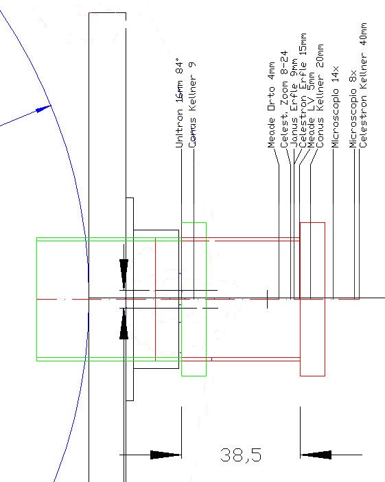
Relative focus position of a eyepiece group. The focuser all entered is drawn in green, while the location of all mined and in red. The total excursion of the focuser is of 38.5mm
To make a correct cutting length of truss tubes, in this case it was necessary to size the trellis so as to be able to bring into focus on Dobson, the first left eye (Unitron 16mm 82° FOV) putting it in the focuser position all inserted.
The cutting of the tubes of the lattice is not an easy task to accomplish with the means of amateur fortune. But with a little patience and organization you can.
METHOD “VERTICAL“
Is’ a usable method for telescopes that have focal lengths up to about 1800mm.
In my experiments (not comfortable) I proceeded bringing the night in the open base of the telescope "at rest", ie with the mirror in horizontal position aiming at the zenith, and once inserted into the focuser indicated “first” eye, fully inserted in focuser, I proceeded to manually to keep the in optical axis the secondary cage, while looking through the eyepiece trying to find the height from the ground which would allow the view summarily focus of a star among those visible at that moment at the zenith.
NOTE: obviously, for telescopes up to 1800mm focal length, the star sought will focus holding the case secondary to a height compatible with that of the person who handles the case of the secondary. And this is justified why this method is applicable to the focal length. because over that length should climb a ladder. It is therefore safer to use homologous method HORIZONTAL.
At that point, in my case “vertical” a person help measured the brief distance from the lower edge of the secondary cash to the ground.
After that I opted to find a mechanical support to hold secondary cage firm and suspended at that height , in order to proceed to a measurement at a little more precise than the length of the trellis bars, precautionally holding it increased by 5 or 6 centimeters.
In my many cases I could always use as a mechanical support, four threaded rods M10, installed as a kind of feet at the base of the secondary cage, with the disadvantage of instability “"dancing"” given the great length, but with the advantage that their continue screw , it possible to adjust the distance from the ground (or fron other reference plane) with great precision.
(in effect since every commercial threaded rod is long only 1 metro, I've got the “long nuts” to connect the head of two threaded rods reaching the desired length).
The method “vertical” described, however, also it has one of its horizontal homologous variant:
HORIZONTAL METHOD
Is’ the variant that “to taste” You can please more, but it is especially valid for telescopes whose focal length exceeds 1800mm.
Instead of using the primary mirror pointed at the zenith, you can perform the same procedure by pointing to the horizon.
Of course, to do what is necessary to position the case of the primary raised from the ground so that the optical axis is horizontal to a height from the ground equal to the height of the eyes that is working dell'astrofilo, with the telescope to present the mirror in a vertical position, aiming towards an object placed on the horizon.
At this point, moving horizontally along the optical axis of the secondary case (linked for example to a self-supporting, usually formed by a double ladder rungs), it becomes too easy to bring the fire of “first” eye, the horizon object.
The horizontal method is better suited for the large telescopes of focal length. intrinsic characteristic of the primary mirrors of large diameter, for which the vertical approach would be impractical, it is not possible to look in the eyepiece and at the same time dangerously slewing case secondary to height above the ground, up and down the steps of a ladder.
APPLIED THE APPROPRIATE METHOD,
And identified the length “lenght” for the # 8 truss tubes, it becomes easy to install them and then refine they length by removing them patiently (one at a time and gradually, with a cutter by hydraulic), a few millimeters of the required tube, UP TO RAGGIUNGERE..FINALMENTE…FIRE FOR THE FIRST EYE. This operation completes the construction of Dobson.
The figure above shows the relative position of the eyepieces fires, we note that, having the Focuser a maximum range of 38.5 mm, and sizing the length of the mast so as to bring down the fire of the first eye, in the desired position of Focuser all turned inward(left position, occupied by the eyepiece Unitron 16mm 82 ° FOV, coinciding with the dimension arrow in the lower left, that indicates the start of 38.5 mm of the Focuser range), They do not remain usable because exceeding the stroke focheggiatura, the last three right eye.
But you can still use hyper, just do not bring their barrel in abutment of the focuser, or equip more “distant” an extension tube.