In this short article, I would like to start introducing the Hartmann test, beginning to describe the principles of operation, the merits and defects, paving the way for further developments and modifications to be able to easily use on the part of us amateur accomplishments during grattavetro.
The Hartmann test was invented by Hartmann (1900) to test the Great Refractor of Potsdam, and it has its antecedent in some ways to measure the eye defects that used a screen with 2 holes to be placed before the eye itself, as described by Tscherning (1894).
This telescope was born in 1899 It has the remarkable opening 80 focal cm 12,2 meters (F15.25), and it is the fourth largest refractor in the world.
And "piggy-back" has a second diameter 50 cm and focal 12,5 meters (F25). The first right of lambda 425 nanometers high., in order to get a better fix on the colors in the photographic plates, and the second corrected on 600 nanometers as it is mainly intended for visual use.
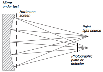
The test uses a mask with a series of holes located near the entrance or exit pupil of the system under examination. The most frequently used screen is constituted by a square or rectangular grid of holes, with one placed in the center, as shown in the figure below, that serves to obtain the return light beams from the mirror, after it has been illuminated by a point source placed in the center of curvature, which they will then be intercepted with an appropriate acquisition system (photographic plate or CCD sensor):
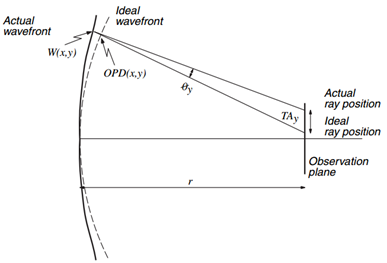
By analyzing the position of the luminous dots it may be able to determine the shape of the mirror surface. The deformations of the wavefront W(x,Y) They are calculated from measurements of the transverse aberrations TAx e Hand (where with TAx e Hand It means the distance between the actual position and the ideal position of the light spot along the directions X e Y,) from the following equations:
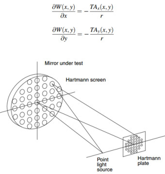
Dove “r"Is the distance of the mirror that must be examined, from the sensor for the acquisition of images.
If the wavefront is convergent, as shown in the first figure in the top, and the sensor of the optical chamber is placed close to the point of convergence, “r"It is the radius of curvature of the wavefront.
In this test, the mask must be carefully centered on the opening of the mirror under examination, and this is especially true in the presence of spherical aberration, which it is the case with aspheric mirrors tested in their center of curvature. A screen decentring, in such a situation, It involves an 'apparent presence of coma.
After the screen has been placed and centered on the mirror, but before acquiring any image of the test, You are necessary to position the point light source, in a manner which is well centered with respect to the mirror in order to avoid the introduction of off-axis aberrations.
This can be done easily if the housing of the point source is of a size such that it can be positioned very close to the sensor for the acquisition of images, and in the vicinity of the center of the mirror. Without the use of elaborate equipment, You can therefore center the source visually evaluating the gap between the source and the return light beam so that they remain within very narrow margins.
For convenience, the point source is placed in a position closer to the mirror with respect to the center of curvature. This position places the image to be scanned over the center of curvature and allows the interception of the converging light in an easier manner.
To facilitate identification of the spots on the photographic plate, it is necessary that the slab or the detector are placed outside the limits of the caustic, also to avoid the intersection of the light beams.
The source can be any dim light, such as to allow a sufficiently long exposure times, to allow to acquire images including the effects of air turbulence average. Or you can acquire a number of different images or frames of a video to mediate the distortions introduced by the increasingly turbulent.
The photographic plate or the detector (example a webcam devoid of the optical part) They must be placed as far as possible perpendicular to the optical otherwise, It introduces of 'fictitious astigmatism in final results.
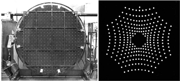
This following is the Hartmann mask positioned on the primary mirror of 2.1 m del Guillermo Haro Observatory telescope, and the corresponding scanned image during the test.
Such a method is able to test the entire surface of the mirror at a stroke and can be used in optics with very pushed focal ratios, that's why it was very used to test mirrors the large professional observatories around the world, although nowadays is more widespread a variant of this test, ie the Shack-Hartmann test (test practically only used by professionals as it requires special equipment with microlenses not easy to find).
E ', however, evident that for obtaining the position of the center of each luminous dot (ben 341 image above) and the relative data reduction is necessary to have special software to avoid having to employ a very long time before you can get to get results.
Software that are generally very difficult to find, at least for amateur use, even if one of them you can find it here : 2D Hartmann test
(unfortunately this link is no longer active for a couple of regions. I leave the same should he re-opened, because, unfortunately,, I could not find on any other site this software. The link you can find it also in the pages of “Stellafane” in the section “Test reduction software”).
This roundup of information were found between the pages of the bible of optical tests that the "Optical Shop Testing" and although from the information does not seem a kind of simple test to run and operate an amateur grattavetro may be starting to use this method but in a simplified manner, or with a mask having windows only arranged along a diameter of the mirror.
In the next article I will report an example of this simplified method or today even I use during processing, in lieu of the Foucault test (less objective) that now use only to verify the goodness of the surface finish (rugosity, signs etc.).